The Power Pwn Clone
2.219
12
3
Introduction: The Power Pwn Clone
This proof-of-concept hack was inspired by the now discontinued Power Pwn (and this). Originally $1,195, you can build a modernized version for less than $100.
The result is a power strip that functions as a very stealthy pen testing drop box.
Recommended Skills:
Basic electrical and electronic soldering and wire stripping
Basic working knowledge of electrical and electronic systems
Basic understanding of Ethernet wiring
Moderate to advanced understanding of computers and technology
Materials:
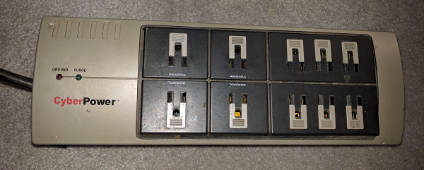
A power strip with Ethernet surge protection, large enough to house a Raspberry Pi 2 circuit board
A Raspberry Pi 2 (You can also use a Raspberry Pi 3.)
A micro SD card 8GB or larger
A small thin 5V 1A USB power adapter (Squarish ones like the ones from the iPhone are small but too thick.)
An Ethernet cable, 2 ft. or longer
A working computer (Windows or Linux is preferable) with an SD port and an adapter for a micro SD card (Or a compatible micro SD USB adapter.)
An HDMI capable monitor or TV and an HDMI cable (To test boot the Raspberry Pi.)
Tools:
A soldering iron and solder
Needle-nose pliers
A utility knife/razor
Wire snips
A multimeter
A hot glue gun is helpful but not necessary
A Dremel tool with a small saw is helpful but not necessary
:::
DANGER, WILL ROBINSON (seriously):
Also be very careful with the electronic components used in this project. Static electricity will fry a circuit board. Take proper precautions.
Step 1: Remove the Surge Protection Circuit Board
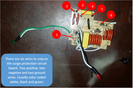
Open the power strip and snip the wires that go into and out of the surge protection circuit board that's inside.
Step 2: Make As Much Room As Possible for the Raspberry Pi
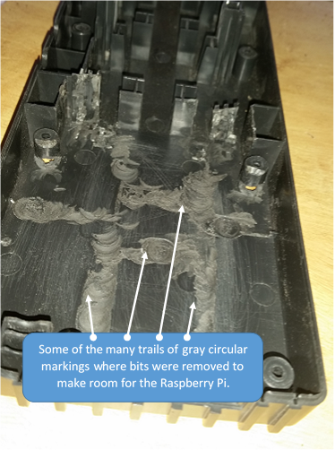
Use a Dremel tool and/or a utility knife and needle-nose pliers to remove as much plastic as possible from the inside of both halves of the enclosure for the power supply to make as much room as possible for the Raspberry Pi. Retrofitting the Raspberry Pi and its power adapter is one of the most challenging tasks in this project.
Step 3: Remove the Circuit Board From the 5V USB Power Adapter
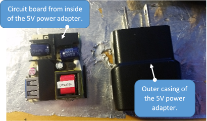
The outer casing and prongs aren’t used so don’t worry about damaging them. I used a small flat-headed screwdriver and a pair of pliers to pry the circuit board from my adapter. Your adapter may require other tools and methods. Once the circuit board is removed, identify and label positive and negative. This circuit board will eventually be wired directly to the 110V rails inside the power strip to power the Raspberry Pi so be very careful and take whatever time you need to label them correctly.
Step 4: Cut and Strip the USB Cable - Part A
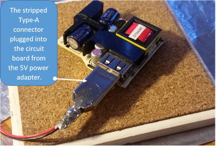
Cut the USB cable about 4 inches from the end with the Type-A connector. Then strip it and snip the two data wires, leaving the black and red power wires. Lastly, plug it into the power adapter.
Step 5: Cut and Strip the USB Cable - Part B
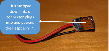
Cut the USB cable about 4 inches from the end with the micro connector. Then strip it and snip the two data wires, leaving the black and red power wires.
Step 6: Reconnect the Surge Protection Board
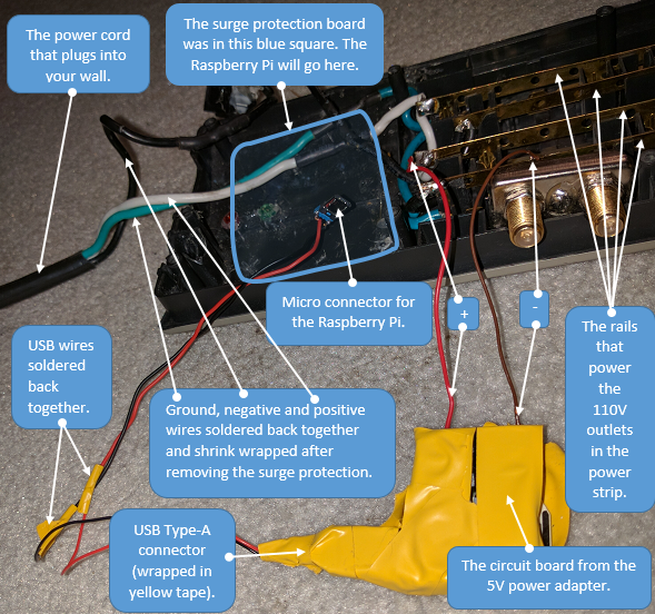
Solder back together and shrink wrap the positive, negative and ground wires we snipped from the surge protection board in step 1. Next, solder the red and black wires of the USB cable for the 5V adapter back together. (See pic) Then, solder two, four inch pieces of the leftover USB wires from positive and negative on the power rails to the 5V power adapter. Finally, insulate all exposed metal (in my case with yellow electrical tape) and solder the wires from the + and - leads on the 5V adapter to the corresponding rails (+ and -) in the power supply. Reconnecting the power switch is optional.
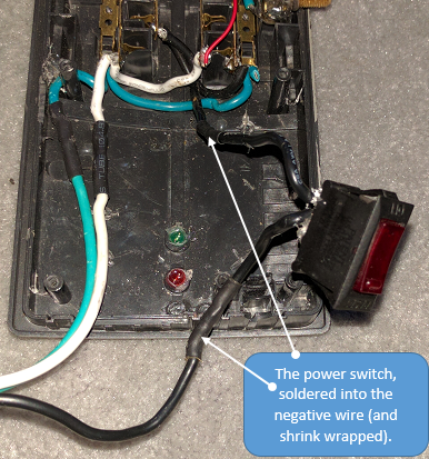
Step 7: Solder the Power Switch Back in (optional)
If you don’t care about having a working power switch, just solder the negative wire back together directly.
Step 8: Prep and Solder the Ethernet Cable
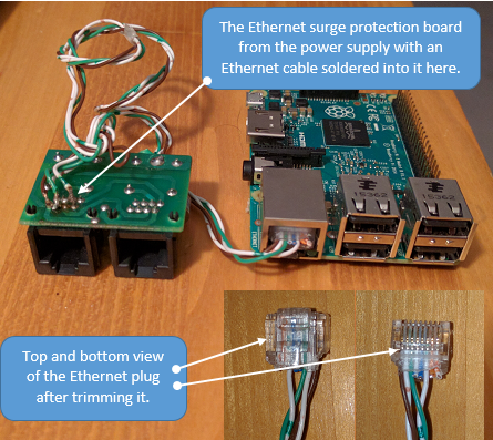
Prep and solder the Ethernet cable to the Ethernet surge protection board inside the power strip. First, compare your wire to the different Ethernet wiring standards and find the one that matches yours. Then use a multimeter to determine where to solder them to. If necessary (to access the solder points), remove the board from the power strip. An Ethernet cable allows direct access to the target network vs Wi-Fi which requires a password that you may not have. You can skip to the next step if you’re okay with Wi-Fi only.
Measure to make sure the cable is more than long enough to go from one end of the power supply to the other. Cut off and discard the rest, strip the sheathing and snip the four unneeded wires per your wiring spec. (If you have enough room you can leave all eight wires.) Then solder the remaining four wires to the four matching solder points on the Ethernet surge protection board.
Finally, if necessary, trim the Ethernet plug. At least in my case, the Ethernet plug stuck out too far to fit inside the power strip after plugging it into the Raspberry Pi.
Step 9: Install Kali Linux on the SD Card
Step 10: Test Boot the Raspberry Pi and Configure It for Remote Access
Connect a USB mouse, keyboard, and HDMI capable monitor to the Raspberry Pi. Then plug it into a power source to boot it. (There’s no power button or switch on the Raspberry Pi 2 so plugging it in is the only way to boot it.) Test Internet connectivity by opening Ice Weasel and doing a Google search. Then configure Kali for remote control and monitoring. (There is a good explanation of how to do this here.) After testing, make sure to initiate a shutdown from within the operating system or it may not boot next time it powers on. In other words, don’t just unplug it to power it down.
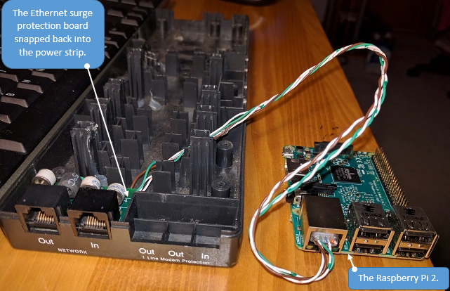
Step 11: Reinsert the Ethernet Surge Protection Board
If you had to remove it to solder wires to it, snap the Ethernet surge protection board back into the power strip.
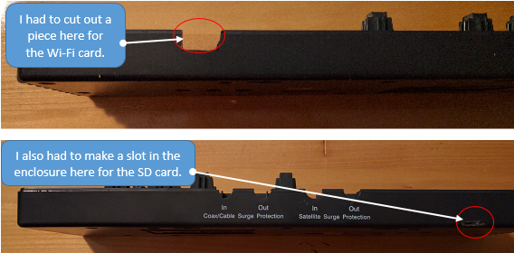
Step 12: Make Any Necessary Accommodations in the Power Strip Case
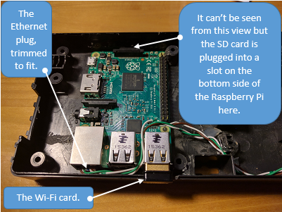
If you haven’t already, check to make sure the Raspberry Pi will fit where the surge protection was removed and if necessary, make accommodations in the power strip for it. Two things wouldn’t fit in the power strip I used - The SD card and the Wi-Fi card.
Step 13: Install the Raspberry Pi
Don't force anything. Take your time and make any necessary changes.
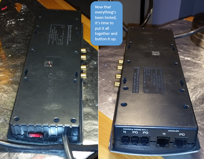
Step 14: Button It Up (and Have Some Fun With It)
Getting everything to fit is easier said than done. Be patient. When you're ready,
https://www.kali.org/category/tutorials/







We have a be nice policy.
Please be positive and constructive.