Sunday, August 6, 2017

SENSITIVE FIRMS LIST

Acquisition Domain:
  • ACT-I
  • AMDEX Corp.
  • B3 Solutions
  • BMK Consultants
  • Bowhead Systems Management
  • Culmen International
  • Davis-Paige Management Systems
  • Domain X Technologies
  • ERP International
  • Goldbelt Raven
  • JRAD
  • Markon Solutions
  • Millennium Corporation
  • MLT Systems
  • Nexagen
  • Patricio Enterprises
  • SAMS
  • Sentek Global
  • SIM
  • Syneren Technologies
  • UCS
  • USI
B&A Domain:
  • BCF Solutions
  • Celerity Government Solutions
  • Deloitte Consulting
  • ECS
  • Engility Corp.
  • Kalman & Co.
  • Millennium Corp.
  • SAIC
  • SAMS
  • TASC
  • Tecolote Research;
E&T Domain:
  • Alion Science and Technologies
  • Booz Allen Hamilton
  • CACI Technologies
  • Camber Corp.
  • Engility Corp.
  • JRAD
  • KASTLE
  • SAIC
  • Schafer Corp.
IT Domain:
  • Alion Science and Technologies
  • AMDEX Corporation
  • Booz Allen Hamilton
  • Camber Corp.
  • Dovel Technologies
  • DSA
  • Engility Corp.
  • ERP International
  • Millennium Corp.
  • Noblis
  • SAIC
  • Schafer Corp.
  • TASC
Logistics Domain:
  • Booz Allen Hamilton
  • CACI Technologies
  • Camber Corp.
  • Engility Corp.
  • ERP International
  • MacB ESI
  • Millennium Corp.
  • Patricio Enterprises
  • SAIC
Medical Domain:
  • Booz Allen Hamilton
  • ERP International
  • Noblis
  • SAIC
  • TASC
  • Tauri Group
One of the sounding topics that has been being argued recently is the Fiber-Based Communication Systems “the hacking possibility”. Is it possible to hack the fiber optical signals and take a copy of them? In addition, even if that is possible theoretically, is it possible for the hackers to go further and re-build the information from inside the optical signal?
Avoiding losing more time arguing the gap between the theoretical possibility and the real and practical facts, the easy way to build a solid and confident decision regarding any changes that the companies and institutions might take, which is likely expensive and interrupting, is to return the things back to their basics. Let us go through a review of what is going on inside the fiber communication system and see if it is possible to hack the optical signals.
The fiber communication systems convert the information into light signals through a series of digital communication processes and functions, and then send the light signals into the fiber strand.
The fiber strand consists of two layers of different refractive indexed glass, that difference in the indexes enables the transmitted light to reflect back and forth until it reaches the end of the strand where the light detector can take the signal to the receiving system for manipulation. Figure 1 clarifies what has been explained.
When the fiber strand is bent, a slight amount of the light power is lost and exits the track of the light “the inner core”, as shown in figure 2. When the bending radius decreases, the amount of lost power increases, until no more power can be received at the end, which can happen at very small bending radius. However, bending of the fiber should be avoided, and if it is necessary it mustn’t exceed the critical radius of the fiber, which is provided with the fiber data sheet.
 Getting back to our main topic “Hacking the Fiber Signals”.
The light signal is a beam of light generated using Light Emitting Diode (LED), or using LASER sources.
To receive the signal at the remote end successfully, the system must satisfy the following:
  • The received power must be relatively strong enough, determined by the vendor who specifies the receiver power sensitivity.
  • The detector input-spot must be very clear and perfectly aligned with the fiber connector.
One hacker claims that his setup is capable of detecting the lost light power, which is caused by bending the fiber strand. Theoretically, there is a certain amount of power lost, but it is very small in value, and the alignment tends to impossible to get the signal detected and copied. Hence, given the strict alignment and sufficient power requirements, it is not as-easy-as-said to copy the optical signals. 
In addition, and as we know, the fiber cables, especially the outdoor cables are strictly protected using multiple layers of different materials, including steel armoring. Assuming the hacker was able to break all the physical barriers to reach the fiber cable itself, he must open the cable, and remove all the protections until he reach the fiber strand. After that, he must strip the strand and reach the glass cladding, and he must be at the site with his extraordinary tools, which can detect a very weak optical signal without any alignment.
 Assuming the hacker did all of the tough steps mentioned above, detecting the optical signals doesn’t mean hacking the information at the higher layers, as it is only a carrier signal and not the information itself.
The optical signals come in many types and with different specifications, different wavelengths, and many other sensitive values. Hence the hacker needs hardware tools with matching design to detect and demodulate the physical optical signal, plus the hacker needs soft tools that can rebuild the information from inside the optical signal.
If-and only –if the hacker succeeds in getting a copy of the optical signal, the information inside the optical signal could be Ethernet frames, which can be rebuilt using special programs, or it could be telecom traffic and information.
When it comes to the telecom networks, I can safely say that it is impossible, and even a funny thing to talk about hacking multiple lambdas with multilayer-multiplexed and encrypted signals, given the physical protection of the cables.
For the institutions and companies, and for the executives and unspecialized people, such news may create fear and drive for changes, but in my opinion, and practically, we are very very far from hacking an optical signal.
The hackers are challenged to hack a normal fiber network without black boxes and pre-made setups.
The only measure that I can see it necessary is to protect the jointing points along the way of the fiber, which can easily by managed using physical locks.
Keep calm …
Good morning, everybody...welcome back to war! So, who wants diplomatic encryption? who wants to travel abroad with hot shit? Here it is: Step One: Before you board your plane, add another key to your whole-disk encryption (it'll probably mean adding another "user") -- and make it random. By "random," I mean really random: Pound the keyboard for a while, like a monkey trying to write Shakespeare. Don't make it memorable. Don't even try to memorize it.
Technically, this key doesn't directly encrypt your hard drive. Instead, it encrypts the key that is used to encrypt your hard drive -- that's how the software allows multiple users.
So now there are two different users named with two different keys: the one you normally use, and some random one you just invented.
Step Two: Send that new random key to someone you trust. Make sure the trusted recipient has it, and make sure it works. You won't be able to recover your hard drive without it.
Step Three: Burn, shred, delete or otherwise destroy all copies of that new random key. Forget it. If it was sufficiently random and non-memorable, this should be easy.
Step Four: Board your plane normally and use your computer for the whole flight.
Step Five: Before you land, delete the key you normally use.
At this point, you will not be able to boot your computer. The only key remaining is the one you forgot in Step Three. There's no need to lie to the customs official; you can even show him a copy of this article if he doesn't believe you.
Step Six: When you're safely through customs, get that random key back from your confidant, boot your computer and re-add the key you normally use to access your hard drive

Thursday, August 3, 2017

pick a 20 € and check how they matrix the hologram...so, they write the same thing, on two layers and then, print on oppositive directions.

Hi everybody! welcome back to war! So, 2 years ago, we've seen more than 56 aspects of money forgery...after all the study research, yes, basically we can cut a lot of steps on the process, making it easy to anyone do it without having a tipography. Where did I stopped, so I don't print my money myself?


DocuColor Tracking Dot Decoding Guide

This guide is part of the Machine Identification Code Technology project. It explains how to read the date, time, and printer serial number from forensic tracking codes in a Xerox DocuColor color laser printout. This information is the result of research by Robert Lee, Seth Schoen, Patrick Murphy, Joel Alwen, and Andrew "bunnie" Huang. We acknowledge the assistance of EFF supporters who have contributed sample printouts to give us material to study. We are still looking for help in this research; we are asking the public to submit test sheets or join the printers mailing list to participate in our reverse engineering efforts.
The DocuColor series prints a rectangular grid of 15 by 8 miniscule yellow dots on every color page. The same grid is printed repeatedly over the entire page, but the repetitions of the grid are offset slightly from one another so that each grid is separated from the others. The grid is printed parallel to the edges of the page, and the offset of the grid from the edges of the page seems to vary. These dots encode up to 14 7-bit bytes of tracking information, plus row and column parity for error correction. Typically, about four of these bytes were unused (depending on printer model), giving 10 bytes of useful data. Below, we explain how to extract serial number, date, and time from these dots. Following the explanation, we implement the decoding process in an interactive computer program.
Because of their limited contrast with the background, the forensic dots are not usually visible to the naked eye under white light. They can be made visible by magnification (using a magnifying glass or microscope), or by illuminating the page with blue instead of white light. Pure blue light causes the yellow dots to appear black. It can be helpful to use magnification together with illumination under blue light, although most individuals with good vision will be able to see the dots distinctly using either technique by itself.
This is an image of the dot grid produced by a Xerox DocuColor 12, magnified 10x and photographed by a Digital Blue QX5 computer microscope under white light. While yellow dots are visible, they are very hard to see. We will need to use a different technique in order to get a better view.
Faint yellow dots
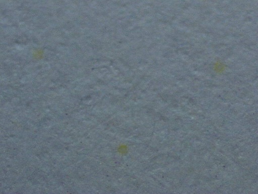
This is an image of a portion of the dot grid under 60x magnification. Now the dots are easy to see, but their overall structure is hard to discern because the microscope field only includes a few dots at a time.
60x
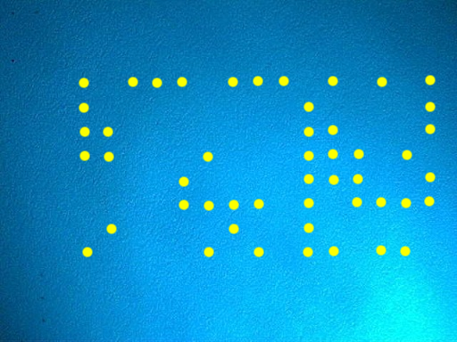
This is an image of one repetition of the dot grid from the same Xerox DocuColor 12 page, magnified 10x and photographed by the QX5 microscope under illumination from a Photon blue LED flashlight. Note that the increased contrast under blue light allows us to see the entire dot pattern clearly.
DocuColor image under blue light and magnification
The illumination is from the lower right; to the upper and lower left of the image, the corners of another repetition of the dot grid are visible.
Here, we use computer graphics software to overlay the black dots in the microscope image with larger yellow dots for greater visibility. (Because these computer-generated dots are significantly larger than the original dots, this image is no longer to scale and is now a schematic representation of the relative position of the dots.)
DocuColor image with large yellow dots added
Finally, we add explanatory text to show the significance of the dots.
Decoding guide
The topmost row and leftmost column are a parity row and column for error correction. They help verify that the forensic information has been read accurately (and, if a single dot has been read incorrectly, to identify the location of the error). The rows and columns all have odd parity: that is, every column contains an odd number of dots, and every row (except the topmost row) contains an odd number of dots. If any row or column appears to contain an even number of dots, it has been read incorrectly.
Each column is read top-to-bottom as a single byte of seven bits (omitting the first parity bit); the bytes are then read right-to-left. The columns (which we have chosen to number from left to right) have the following meanings:
  • 15: unknown (often zero; constant for each individual printer; may convey some non-user-visible fact about the printer's model or configuration)
  • 14, 13, 12, 11: printer serial number in binary-coded-decimal, two digits per byte (constant for each individual printer; see below)
  • 10: separator (typically all ones; does not appear to code information)
  • 9: unused
  • 8: year that page was printed (without century; 2005 is coded as 5)
  • 7: month that page was printed
  • 6: day that page was printed
  • 5: hour that page was printed (may be UTC time zone, or may be set inaccurately within printer)
  • 4, 3: unused
  • 2: minute that page was printed
  • 1: row parity bit (set to guarantee an odd number of dots present per row)
The printer serial number is a decimal number of six or eight digits; these digits are coded two at a time in columns 14, 13, 12, and 11 (or possibly just 13, 12, and 11); for instance, the serial number 00654321 would be coded with column values 00, 65, 43, and 21.
We have prepared a computer program to automate this decoding process. Below, you can interactively enter a dot grid from a DocuColor page and have it interpreted by our program. If you don't have a microscope, a magnifying glass should be a practical substitute.
123456789101112131415
col parity
64
32
16
8
4
2
1
 
EFF does not log the information submitted to this web form or the results it returns. If you prefer, you can download the source code of this program, which we have licensed under the GNU General Public License.

https://w2.eff.org/Privacy/printers/docucolor/