Parts for the 120 VAC main input.
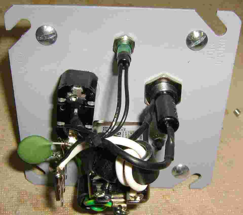
A high-amperage line filter, toggle switch, and fuse holder will be mounted inside a square electrical outlet box. The filtered 120 VAC lines will be mounted on standoffs and distributed to the other transformers.
The little green blob with two leads is an input surge absorber from an old computer switching power supply. It's used to reduce the large surge current when the power is initially applied.
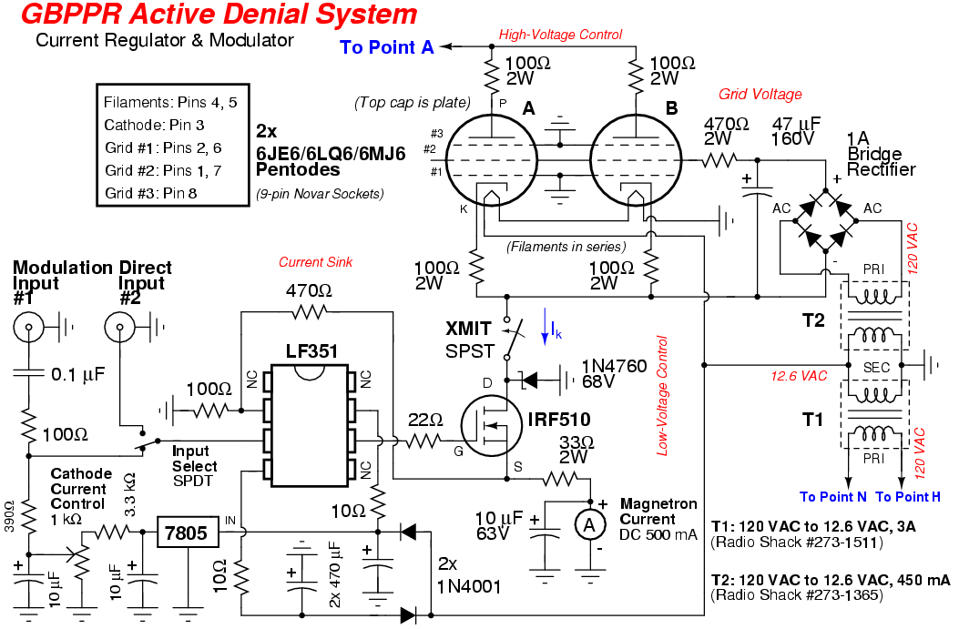
The Radio Shack #273-1511 transformer will provide the 12.6 VAC for the two 6MJ6 tubes (filaments in series) we will be using. It will also provide the +/- power supply for the op-amp in the control circuit.
Rear view of the AC input power panel.
Try to use a single point ground to reduce any ground loops.
There are (optional) ferrite beads on the incoming 120 VAC hot, neutral, and ground leads.
A green neon lamp is used as a power indicator.
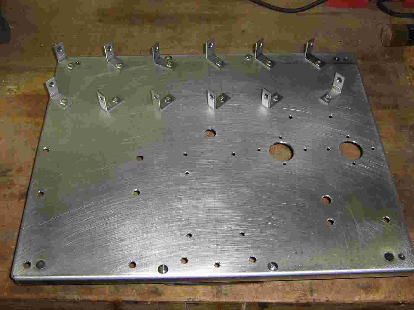
Everything will be mounted to a large aluminium plate.
L-brackets are riveted to the plate, which will be used to mount the twelve electrolytic capacitors making up the high-voltage power supply's ripple capacitor.
Secured electrolytic capacitor.
Twelve 650 µF / 450 VDC electrolytic capacitors will be used.
Put a piece of heatshrink tubing over the L-bracket and wrap the bottom of each capacitor with electrical tape.
Secure the capacitors using hose clamps.
The twelve capacitors ready to go.
Proper high-voltage construction techniques would require a little more space between the capacitors and maybe also mount them on some type of insulator. Oh well...
Wire the capacitors in series (+ to -) with a 100 kohm / 5W resistor across each one for voltage load sharing.
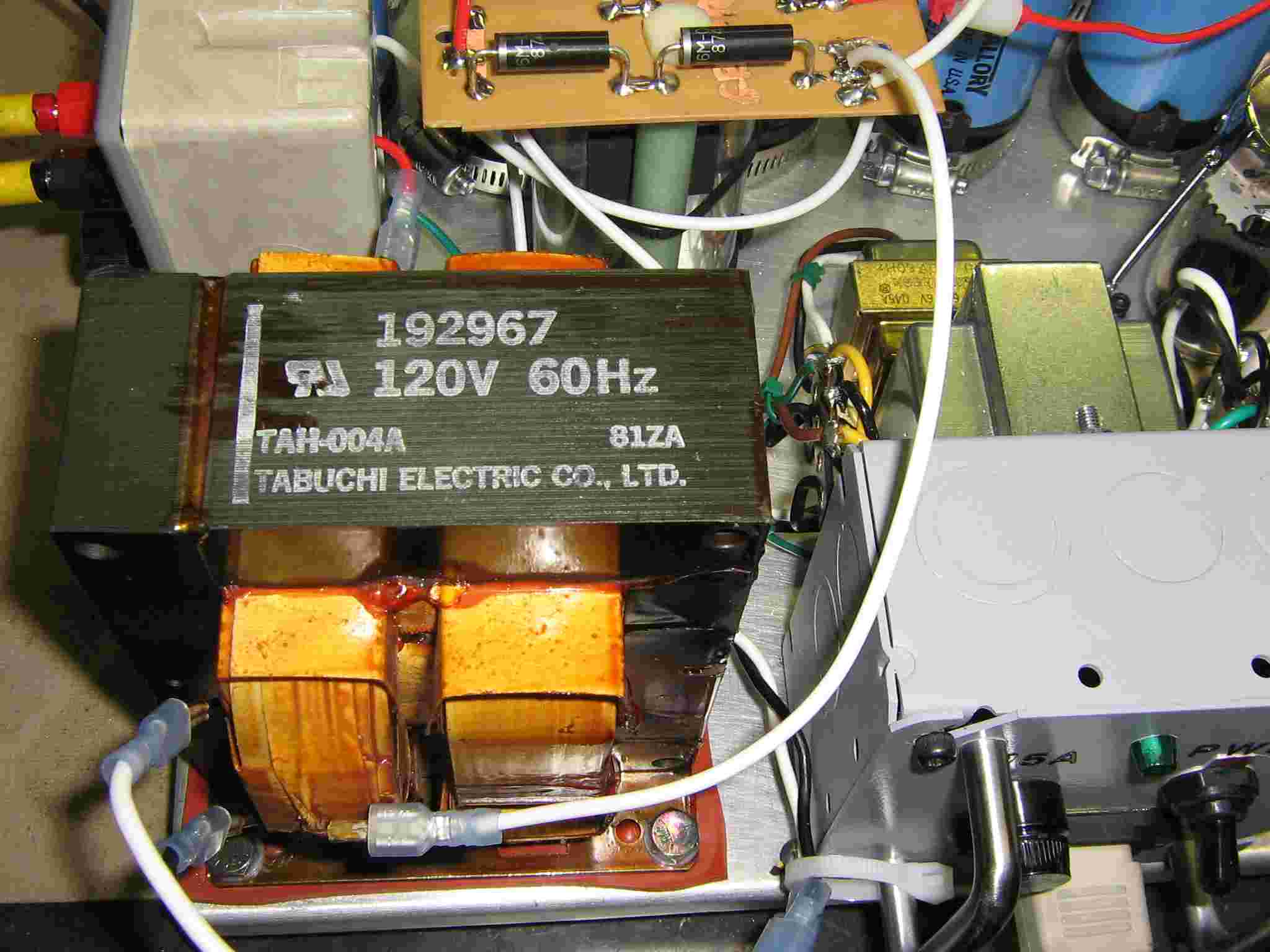
Stock microwave oven transformer.
Its secondary provides 3.3 VAC for the magnetron's filament and the high-voltage winding provides around 1,800 VAC.
Note that one side of the high-voltage winding is connected to the frame of the transformer (ground). This will need to be disconnected and properly isolated.
The magnetic shunts, which are normally installed in a microwave oven transformer, can stay.
On the two bottom spade connectors for the 120 VAC primary input, a resistor/capacitor snubber circuit is used to clamp any high-voltage spikes or kick-backs.
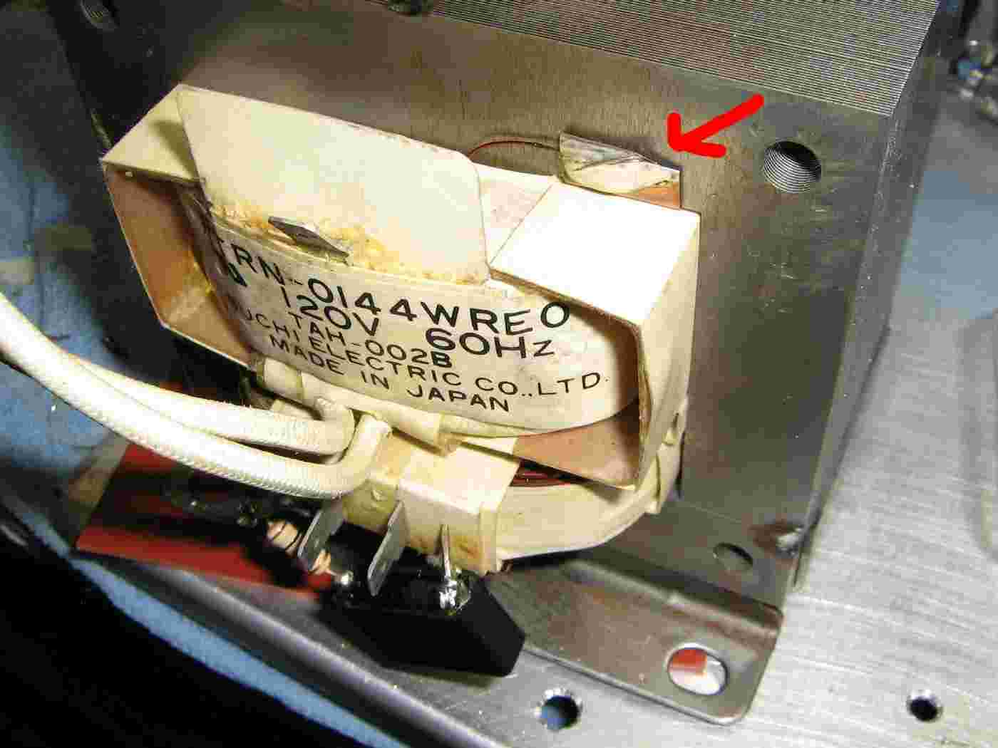
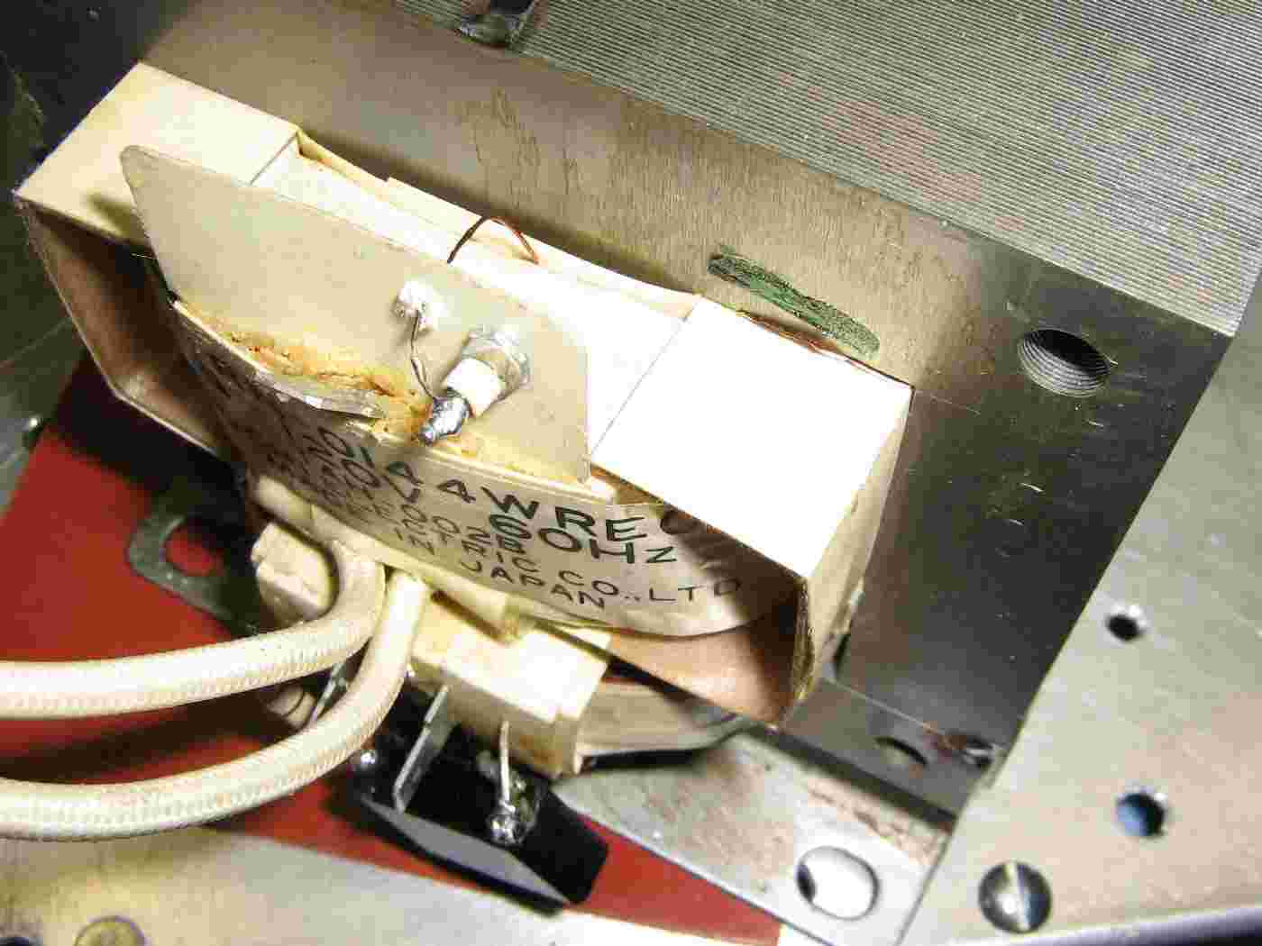
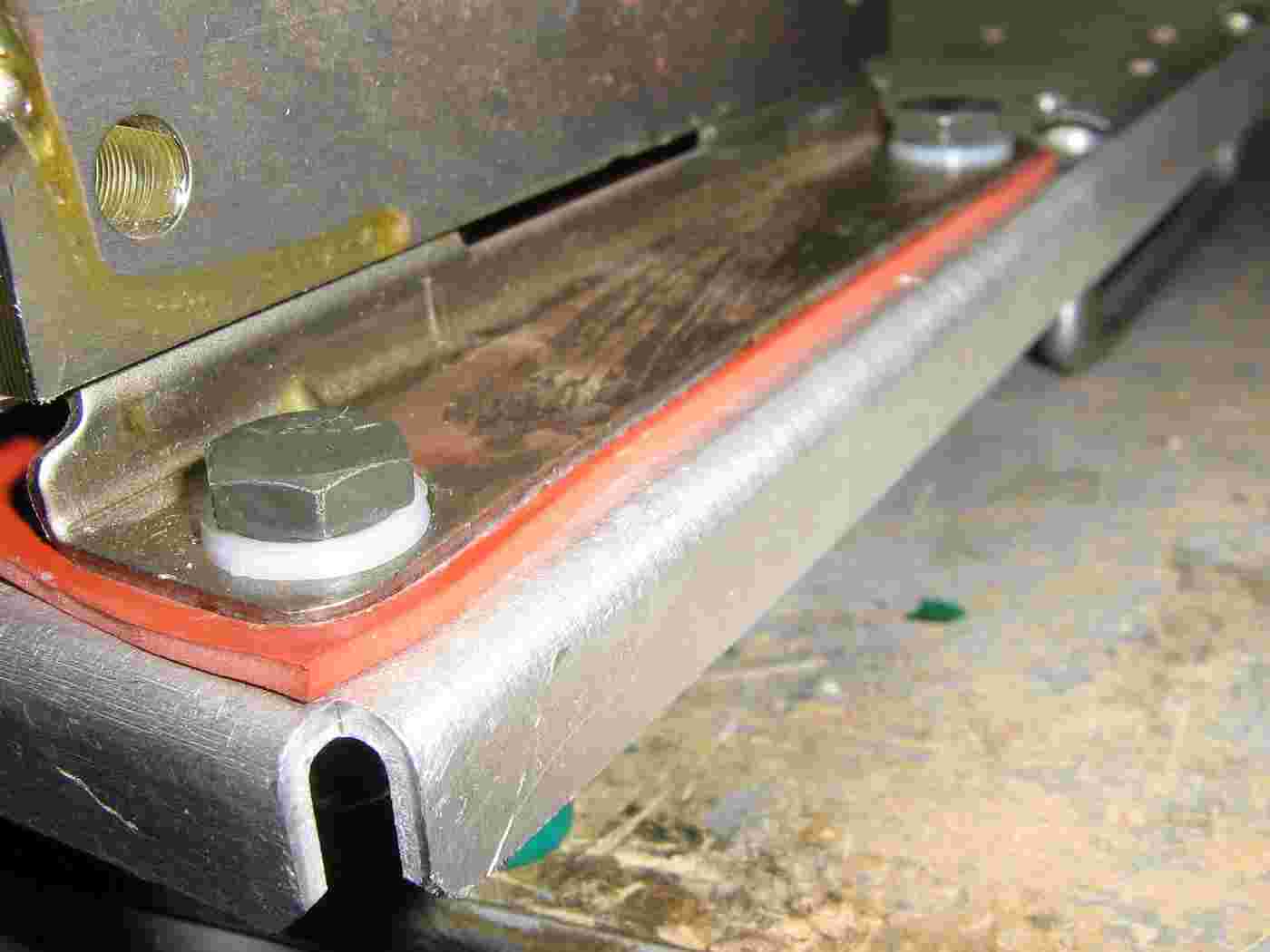
Isolating the high-voltage secondary.
The grounded end was unsoldered and connected to a little stand-off terminal mounted on the transformer's protective cardboard.
Not all transformers will be the same, but they will all have one side of the high-voltage winding tied to ground, either with a screw or a solder tab.
The case of the transformer was further isolated from the chassis ground using a rubber gasket sheet and nylon washers on the mounting bolts.
This is to help reduce any 60 Hz hum, if you'd ever wish to modulate the magnetron's output in the future, so it's not really a requirement.
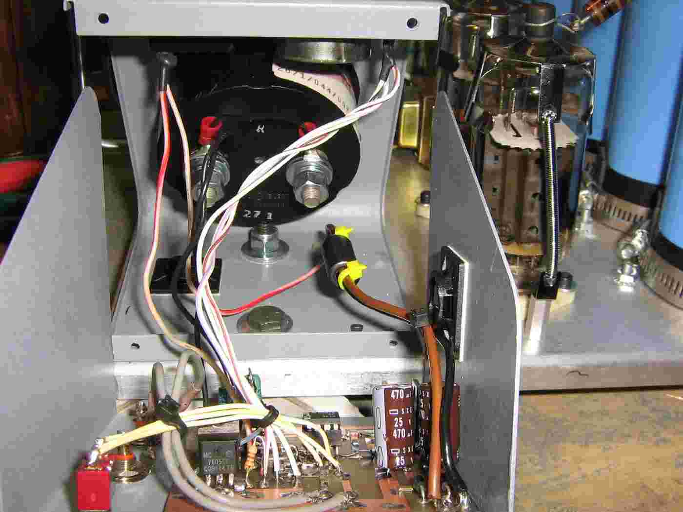
Overview of the 6MJ6's filament transformer (silver-colored - mounted on the electrical box) and also the grid voltage transformer (gold-colored).
The series 0.8 µF capacitor in the voltage-doubling circuit is isolated from ground by Zip-tying it to a plastic rod.
You can also see the high-voltage load sharing resistors (100 kohm / 5W) aross each of the electrolytic capacitors. These will also help to dissipate any stray voltage when the power is off.
High-voltage output from the capacitor bank.
Little spring clips were made to connect the 100 ohm resistors to the top cap (plate) on the two 6MJ6s.
6MJ6s in place.
Optional spring retainers hold the tubes in place.
The tube on the lower-right is the "A" tube, the other is the "B" tube.
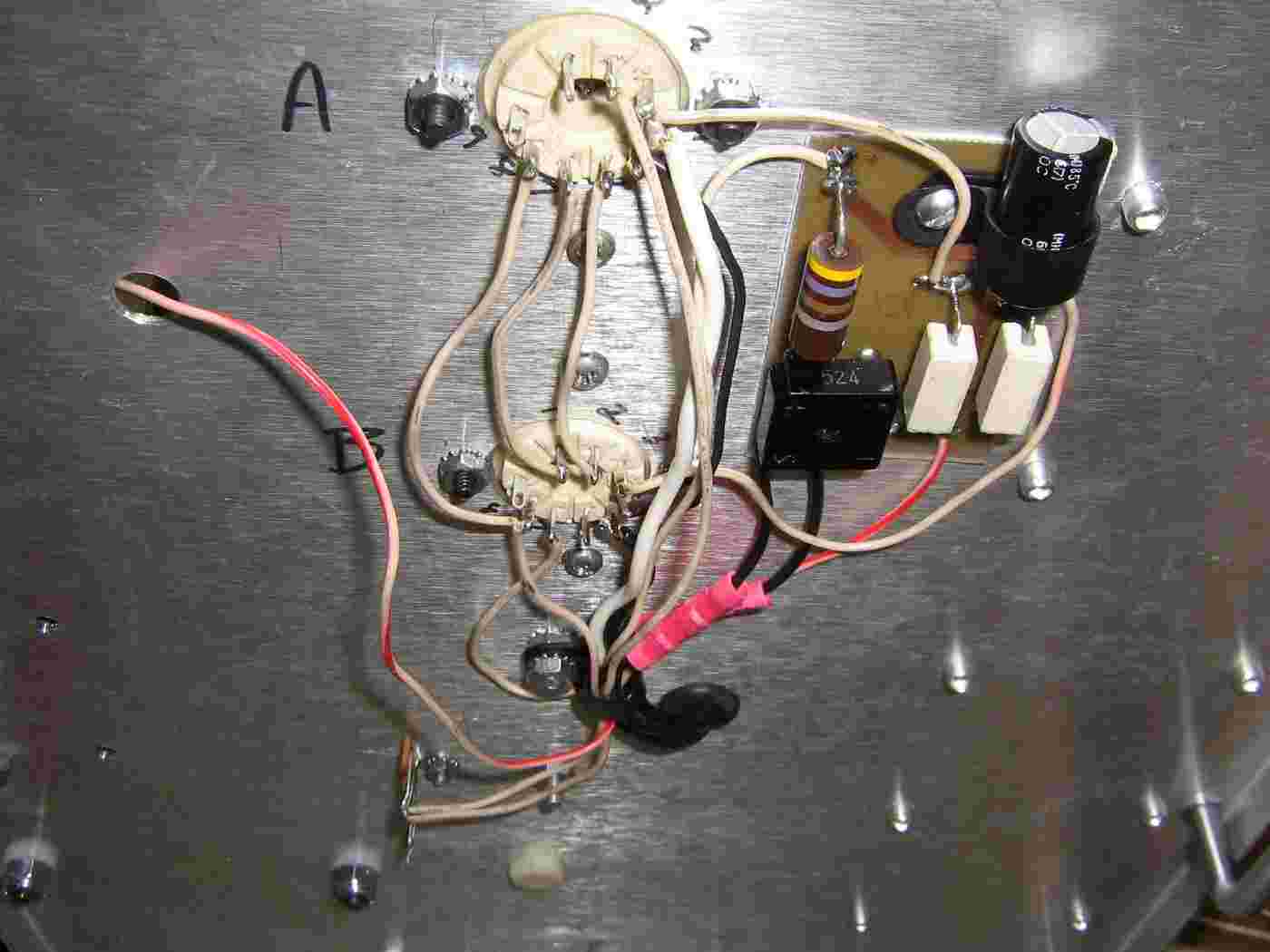
Underside view of the mounting plate showing the tube socket wiring and grid voltage circuit.
The top socket is for the "A" tube, the other is for the "B" tube.
The 6MJ6's have their filaments wired in series so they can be driven directly with the 12.6 VAC secondary from a Radio Shack #273-1511 transformer.
Note the nylon insulation washers on the microwave oven transformer's mounting bolts (lower-left).
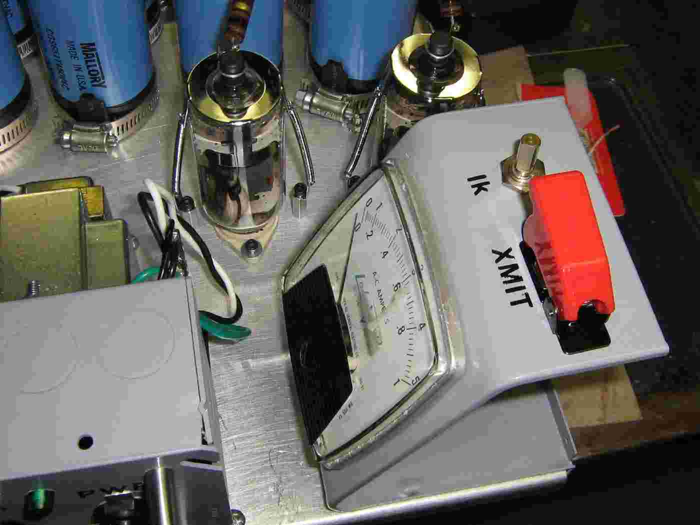
Magnetron current meter, magnetron cathode current control (Ik), and the transmit-enable (XMIT) switch.
The meter is from an old Lab-Volt trainer used in schools. Its full-scale reading is 500 mA DC.
HVPR16-06 high-voltage diodes in the voltage doubler circuit.
Leaving the shunts in the microwave oven transformer also helps to suppress the large surge current when first powered on. This is necessary to protect the diodes from any over-current transients.
Use two diodes in series, as shown, just to be safe.
HVPR16-06 Diode Specifications VR 6,000 Volts IF 550 mA VF10.00 Volts
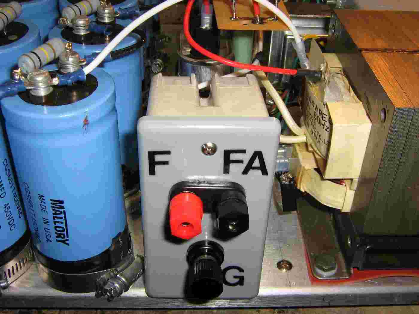
The final high-voltage output connectors will be mounted in a fiberglass electrical box. The magnetron connections will be via banana jacks.
Connect the banana jacks like so. Note that the direct filament winding on the microwave oven transformer usually goes to the magnetron's "FA" terminal. Every schematic or datasheet shows them connected differently, so I don't know on that one...
Also note the isolated ground lug. This ties back to the single point ground in the main incoming voltage electrical box.
Completed high-voltage magnetron connection plate.
Toshiba 2M172J magnetron mounted to the horn assembly built in GBPPR 'Zine, Issue #55.
The horn has a mounting bracket in the rear to allow for mounting at the focal point of a parabolic dish.
A large 120 VAC fan provides continuous air flow over the magnetron's cooling fins.
Raytheon markets their Active Denial System for "riot control."
This one is designed for "Bolshevik control."
"'Nobody wants to be on the wrong side of Ari Emanuel, especially now that his brother is running the White House,' said one television executive, who asked for anonymity to preserve harmony with him."
--- June 9, 2009 quote about Ariel Emanuel, Jewish supremacist Rahm Emanuel's brother, in the New York Times (of all places).
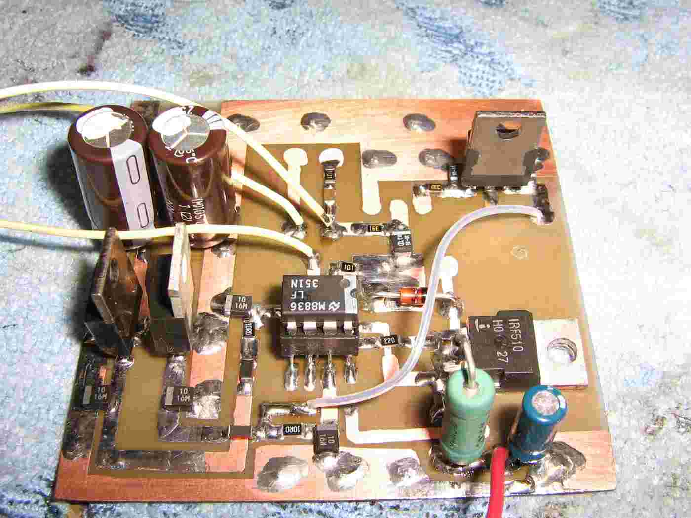
Current sink circuit board.
Differs slightly from the original 73 article due to not having all the same parts. Should work fine though, except for amateur television transmissions.
A LF351 op-amp replaces the circuit's original LF357. The LF351's voltage is regulated via (optional) 7812 and 7912 regulators. An IRF510 N-channel MOSFET replaces the VN66AF.
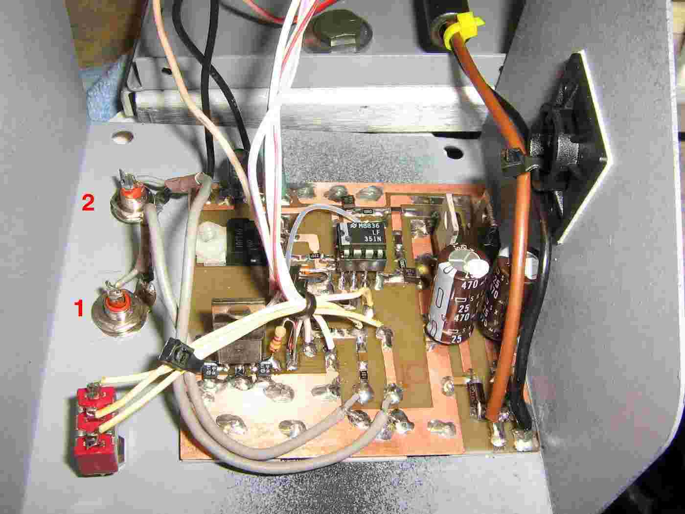
Mounting the control circuit board.
The two phono jack inputs are for external current control and modulation input. These will be for upcoming projects.
The Input Select switch is on the lower-left. The Modulation Input #1 is the phono jack below that, then the Modulation Input #2 (direct) phono jack.
Final wiring showing the current meter, transmit switch, and 1 kohm current control potentiometer.
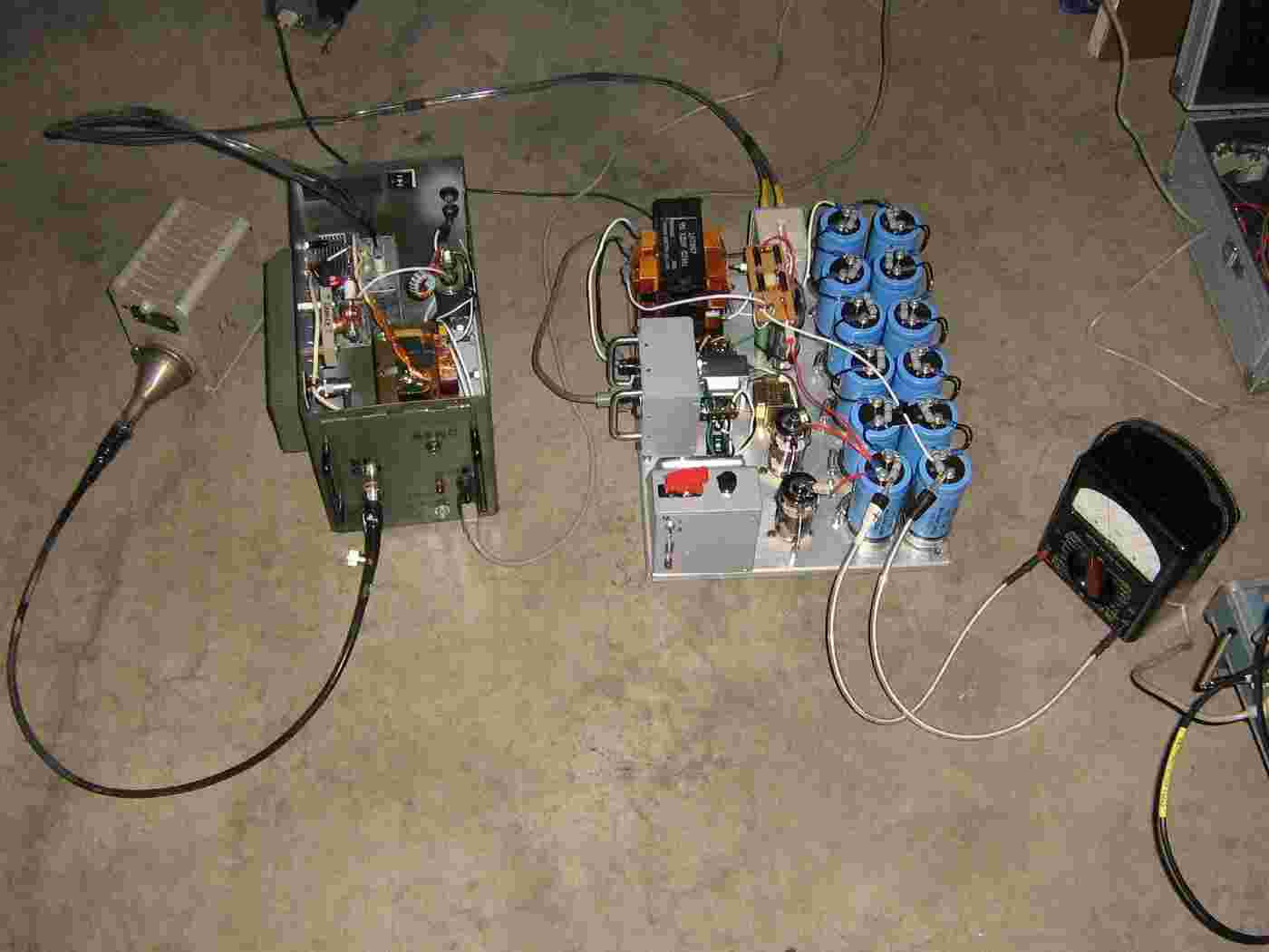
Outside test setup.
Wasn't sure if it would work or not, but remarkably, everything did check out.
An Atari Lynx is used as a RF output indicator.
The high-voltage lines to the magnetron are run through vinyl tubing for extra insulation.
Then it blew up...
Microwave oven transformers are not really designed for continuous current operations, or for use in "real" high-voltage power supplies.
As you can see here, the high-voltage secondary winding arced over. Try to find a microwave oven transformer that is physically large or has been coated with some type of resin or sealant.
Back up and running with a new microwave oven transformer.
This transformer has been coated with some sort of "goo" to help prevent high-voltage arcing.
All microwave oven transformers are basically the same, so swapping them out should be no problem. They all seem to have slightly different mounting or wiring configurations, though.
A good secondary high-voltage winding on a microwave oven transformer will usually have a DC resistance between 50 and 120 ohms or so. The filament winding will have very low DC resistance, often below 1 ohm. You can use this to check the windings before hand.
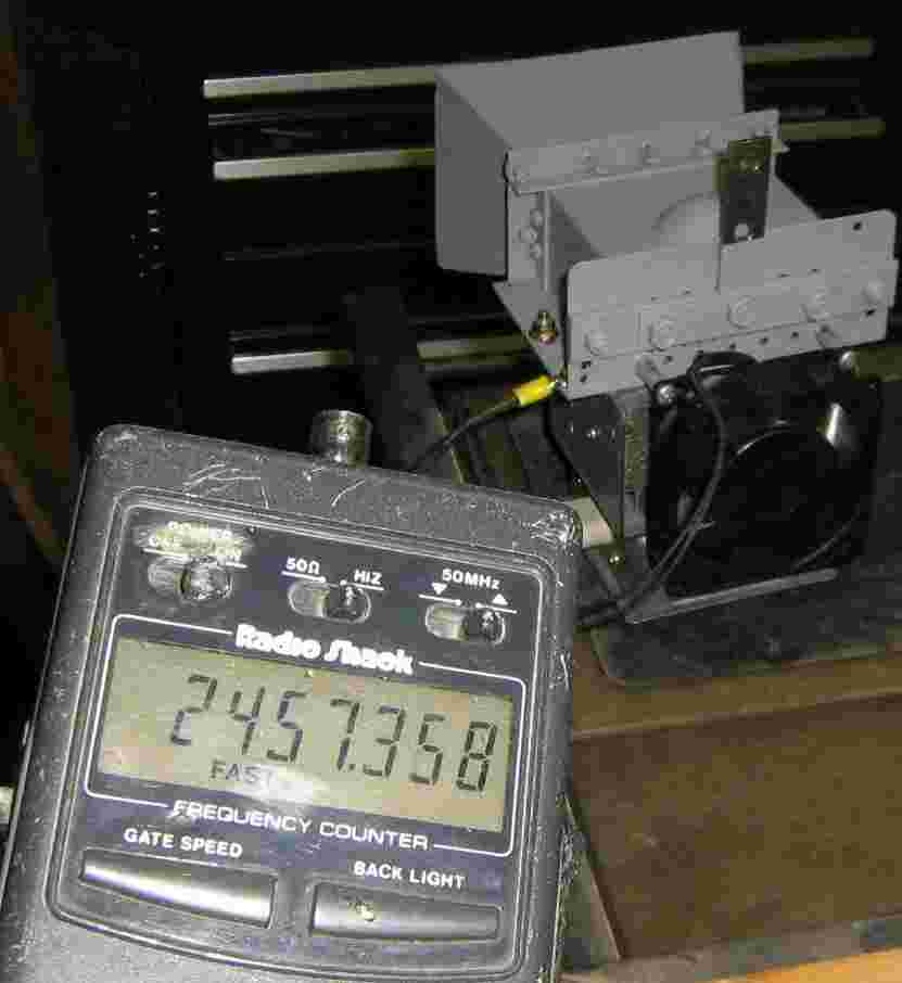
Is it bad when you can get a frequency counter reading, with no antenna, and standing behind the horn?
This magnetron is being run into a 50 ohm load for testing with a spectrum analyzer.
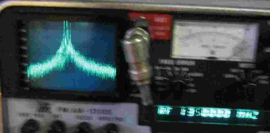
Spectrum analyzer view of the magnetron's RF output transverted (2.278 GHz LO) to fit the range of an IFR service monitor. The spectrum display is 1 MHz per division.
On the left, is the output of a Litton 2M167 magnetron. The meter is reading a center frequency of "135.0 MHz," but this converts to an actual output frequency of 2.413 GHz. Note the output is about 1 MHz lower than the center reading. This magnetron was run into a 50 ohm load via a homebrew waveguide-to-coaxial adapter.
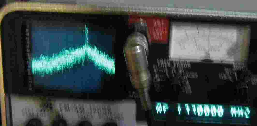
On the right, is the output of a Toshiba 2M172 magnetron. The meter is reading "177.0 MHz," and the signal is about 1.5 MHz higher than the center frequency. The final output frequency is around 2.4565 GHz. This magnetron was run into an open horn, so there was alot of background RF noise, which raises the noise floor on the analyzer.


