Thursday, July 30, 2015

Optical Emission Security – Frequently Asked Questions
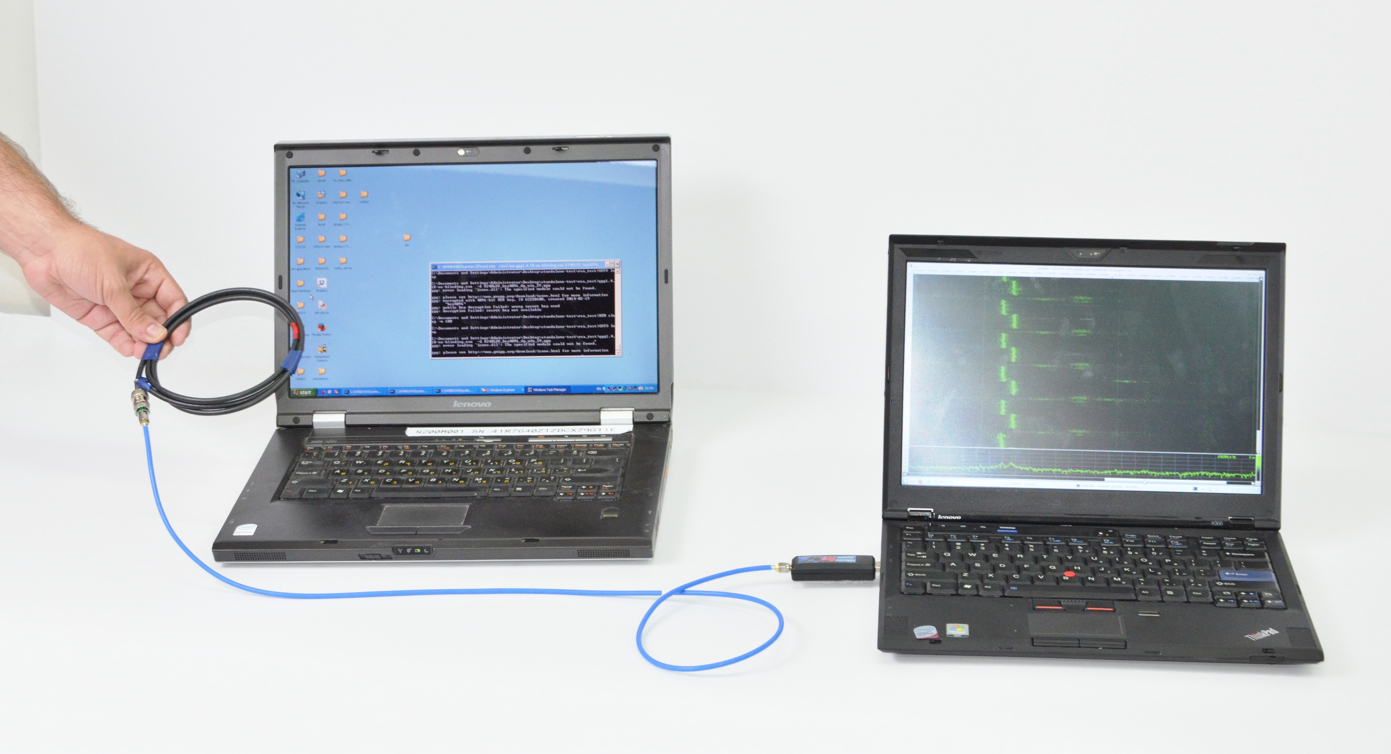
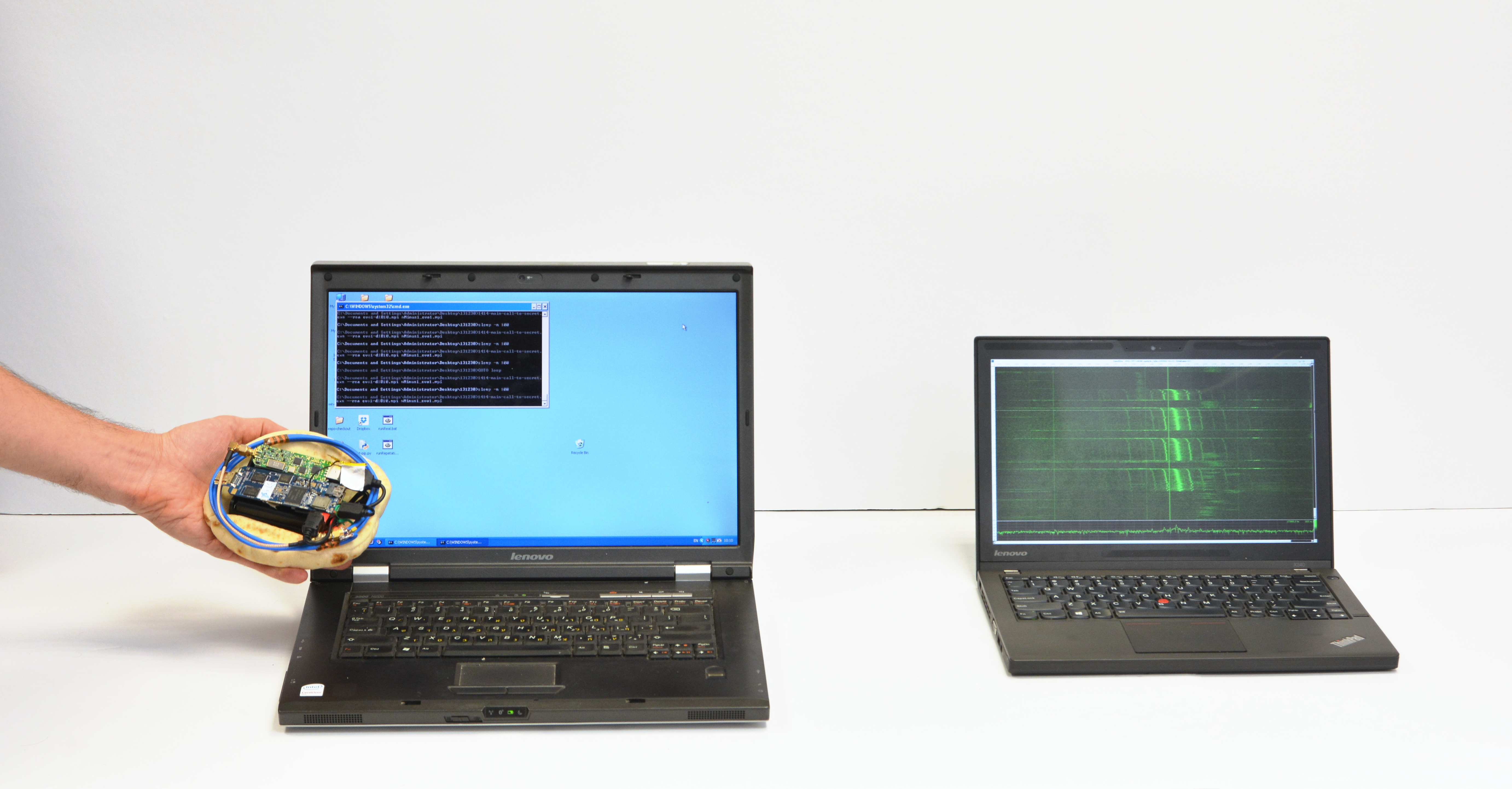
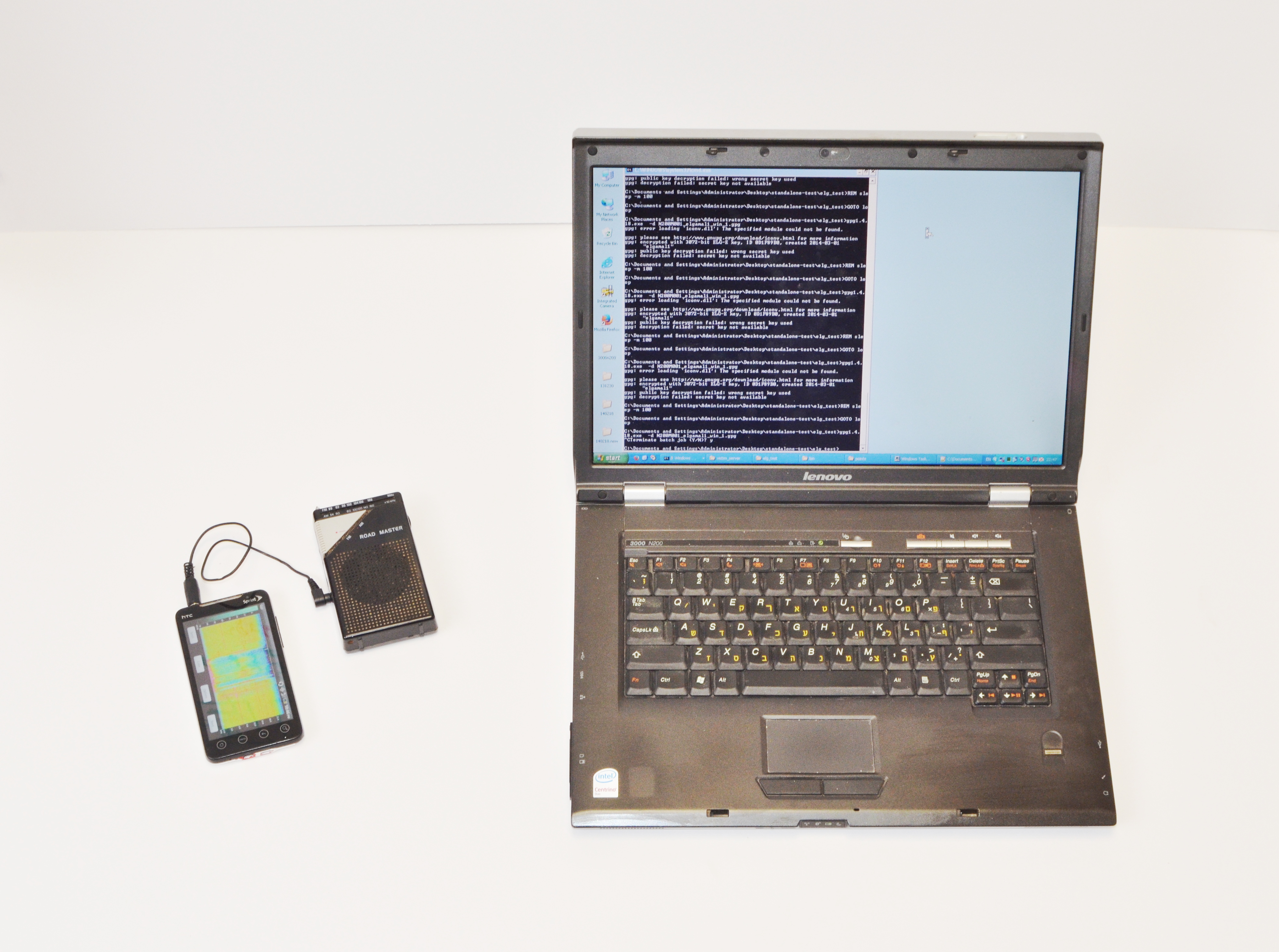
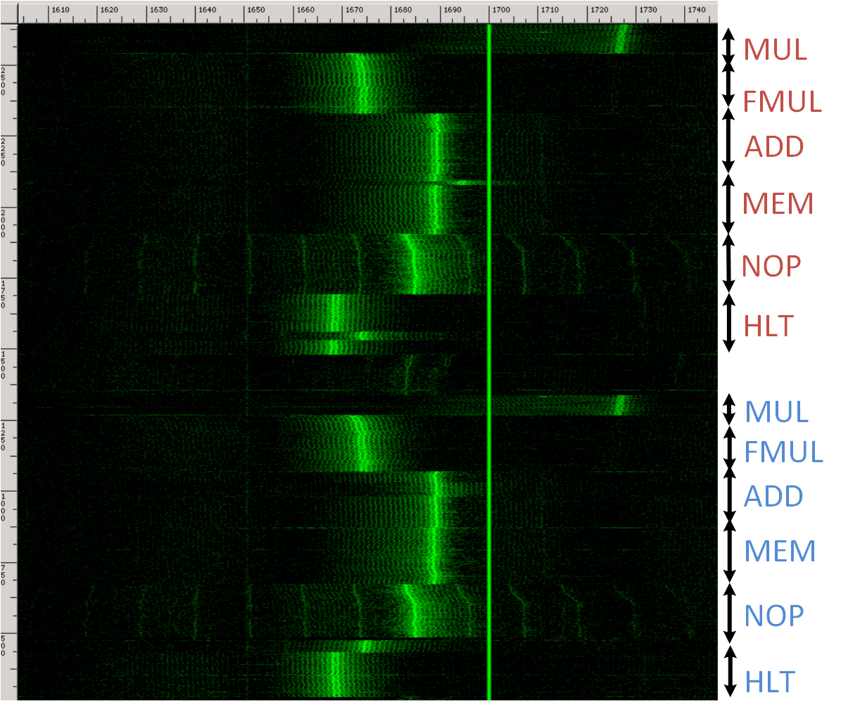
Markus Kuhn In the paper
Optical Time-Domain Eavesdropping Risks of CRT Displays,
2002 IEEE Symposium on Security and Privacy, Berkeley, California, May 2002.
I describe a new eavesdropping technique that reconstructs text on computer screens from diffusely reflected light. This publication resulted in some wide media attention (BBC, New Scientist,Wired, Reuters, Slashdot). Here are answers to some of the questions I have received, along with some introductory information for interested readers looking for a more highlevel summary than the full paper, which was mainly written for an audience of hardware-security and optoelectronics professionals. Q: How does this new eavesdropping technique work? To understand what is going on, you have to recall how a cathode-ray display works. An electron beam scans across the screen surface at enormous speed (tens of kilometers per second) and targets one pixel after another. It targets this way tens or hundreds of millions of pixels every second to convert electron energy into light. Even though each pixel shows an afterglow for longer than the time the electron beam needs to refresh an entire line of pixels, each pixel is much brighter while the e-beam hits it than during the remaining afterglow. My discovery of this very short initial brightness in the light decay curve of a pixel is what makes this eavesdropping technique work. An image is created on the CRT surface by varying the electron beam intensity for each pixel. The room in which the CRT is located is partially illuminated by the pixels. As a result, the light in the room becomes a measure for the electron beam current. In particular, there is a little invisible ultrafast flash each time the electron beam refreshes a bright pixel that is surrounded by dark pixels on its left and right. So if you measure the brightness of a wall in this room with a very fast photosensor, and feed the result in another monitor that receives the exact same synchronization signals for steering its electron beam, you get to see an image like this: raw rasterized photomultiplier signal You can already recognize some large characters and lines of text, but the long afterglow of the phosphor still distorts the image significantly. A mathematical signal processing technique known as deconvolution can now be used to undo this blurring to some degree: deconvoluted photomultiplier signal This magnification shows that even small font sizes become readable: magnified excerpt Q: How far away does this work and what is "shot noise"? The amount of noise that a constant light level introduces into a photo sensor is proportional to the square root of the light intensity. This is because light does not arrive as a continuous stream of energy, but in small countable energy packets (photons). The number of photons that arrive during some fixed time interval varies randomly, and this variation is described by what statisticians call Poisson distribution. It is a characteristic of the Poisson distribution that if you expect on average N photons to arrive, then the average difference between N and the actual number of photons that you got will be sqrt(N). This fluctuation is in electronics called shot noise. Shot noise means, that in order to get a signal, the number of photons that you receive per pixel from the CRT must be at least the square root of the number of photos that you get from other light sources such as the sun or light bulbs. As the eavesdropper moves further away, the receiver will be able to capture fewer photons. Even though the ratio between CRT photons and background photons might remain roughly the same, the square root of the number of background photons will grow relative to the CRT photon count with distance, thereby reducing the signal-to-noise ratio. The paper contains the mathematical details for calculating the signal-to-noise ratio at various distances, and in one example calculation in which I used what I hope are practically interesting parameters for background light, and size of the sensor, I ended up with a maximum eavesdropping distance of in the order of 50 meters. It is important to understand, that this figure is just one example calculation result. Changes in the background light, the pixel frequency, the required signal-to-noise ratio, or other parameters will lead to significant different distances. Having said that, I do believe that the outcome of this study can be described as that eavesdropping a computer monitor with common font sizes via light reflected from a wall seems feasible from a building on the other side of a street if the targeted room is only weakly illuminated. Interested readers will find in the paper enough data and information to perform realistic numeric simulations of an eavesdropping attack in a specific situation. Q: What can eavesdroppers do to improve reception? There are a number of techniques, for example some of those mentioned in the paper are:
  • The eavesdropped videosignal is periodic over at least a few seconds, therefore periodic averaging over a few hundred frames can help significantly to reduce the noise.
  • If you know exactly what font is used, many of the equalization and symbol detection techniques used in modems or pattern recognition applications can be applied to recover the text (remote optical character recognition).
  • Optical filters can eliminate other colours from background light.
  • A large sensor aperture (telelens, telescope) can improve the photon count.
Q: What can I do to prevent reception? There are a number of techniques, for example some of those mentioned in the paper are:
  • Reception is difficult if not impossible from well-lit rooms, in which CRTs do not make a visible contribution to the ambient illumination. Don't work in the dark.
  • No not assume that etched or frosted glass surfaces prevent this technique if there is otherwise a direct line of sight to the screen surface.
  • This particular eavesdropping technique is not applicable to LCDs and other flat-panel displays that refresh all pixels in a row simultaneously.
  • Make sure, nobody can install eavesdropping equipment within a few hundred meters line-of-sight to your window.
  • Use a screen saver that removes confidential information from the monitor in your absence.
Q: What phosphor types reduce the risk and which monitor brands use them? The vendors of colour computer monitor vendors currently do not provide any useful information about what screen phosphor type is used. The designation "P22" found sometimes in datasheets is mostly meaningless, as it describes any combination of red/green/blue phosphors that fulfill the NTSC TV colour specification. For that reason, I have not yet performed a systematic test of different phosphor types currently on the market. Q: What colour combination is most difficult to eavesdrop? A bright background contributes shot noise. In the monitor I tested, the red phosphor had the by far lowest initial luminosity. It emitted a much smaller part of its stored energy in the first microsecond than did the blue and green phosphors. Normal light bulbs emit more red then blue light. Therefore it might seem prudent to place critical text information into the red channel only, while keeping the other to maximum brightness, leading to colour combinations such as cyan on white or green on yellow. However, such low-contrast text display violates ergonomic standards, therefore I would advise against using this approach. In addition, the light from typical red phosphors is concentrated in a few narrow spectral lines, and therefore might be more easily separated by wavelength from background light. Q: Is this really a serious risk? A radio-frequency technique for video display eavesdropping was first described in the open literature by Wim van Eck in 1985. Even though it generated considerable excitement at the time and NATO governments have invested billions of dollars for countermeasures, not a single case of computer crime based on this technique has been uncovered so far, apart from occasional suspicions in some financial institutions that handle information of very high short-term value. This either means that such compromising emanations attacks are practically not used, or if they are used, then so rarely and well prepared that the eavesdroppers never got caught so far. It is my understanding that some major NATO intelligence agencies still do maintain the capability to perform remote RF video display eavesdropping, but I have no idea on how valueable they find such techniques in practice to gather useful intelligence. Compared to radio frequency emanations, the equipment need for optical eavesdropping is somewhat easier to obtain, because suitable commercial RF wide-band receivers are normally rather expensive and export controlled (though obtaining a second-hand one was not entirely impossible, even for a research student, and there are always numerous ways to modify readily availabl low-cost equipment suitably). Photomultipliers and digital storage oscilloscopes on the other hand are rather common laboratory equipment. The feasible eavesdropping ranges in an urban/suburban environment are very comparable for both techniques. Optical eavesdropping is somewhat more restricted in that for the diffuse reflection case, low background illumination is essential to make it work, but on the other hand it leads usually to much better image quality and works not only for text but also for colour images. I would be surprised if optical CRT eavesdropping finds widespread use. The risk is not entirely unrealistic, but it probably should be of primary concern only to those in charge of high-security facilities that are targeted by intelligence agencies or well-funded industrial espionage teams and that have already invested significant effort to close any other known type of security vulnerability. There might also be specialized applications for TV or software licence enforcement targeted against private and commercial consumers. A compromising emanations eavesdropper has to be extremely patient, because it is necessary to wait until the information of interest is displayed or processed by the system, which is often not easy to predict. In most commercial environments, it is for a determined attacker far more easy to break into a facility, get physical access to the storage media and take or copy it, in order to gain noise-free access to all information at once, or to bribe an employee with access to do the same. Unsurprisingly, breakins where all the burglars were interested in was the harddisk of a company's central file server are being reported regularly. For me, this project was mostly driven by academic curiosity. It was a good excuse to learn a lot about optoelectronics and get a photomultiplier to play with. I hope, not only computer security educators and textbook authors will find this demonstration a valuable example for how surprising and unexpected the nature of hardware-security side channels can be. Q: What about LEDs? For devices with RS-232 serial ports, it is customary to provide a status indicator LED for some of the signal lines (in particular transmit data and receive data). Often, these LEDs are directly connected to the line via just a resistor. As a result, anyone with a line of sight to the LED, some optics and a simple photosensor can see the data stream. Joe Loughry and David A. Umphress have recently announced a detailed study (submitted to ACM Transactions on Information and System Security) in which they tested 39 communications devices with 164 LED indicators, and on 14 of the tested devices they found serial port data in the LED light. Based on their findings, it seems reasonable to conclude that LEDs for RS-232 ports are most likely carrying the data signal today, whereas LEDs on high-speed data links (LANs, harddisk) do not. Even these LEDs are still available as a covert channel for malicious software that actively tries to transmit data optically. I expect that this paper will cause a number of modem manufacturers to add a little pulse stretcher (monostable multivibrator) to the LEDs in the next chip set revision, and that at some facilities with particular security concerns, the relevant LEDs will be removed or covered with black tape. The data traffic on LEDs is not a periodic signal, and therefore, unlike with video signals, periodic averaging cannot be used to improve the signal-to-noise ratio. The shot-noise limit estimation technique that I used to estimate the CRT eavesdropping risk can even more easily (because no deconvolution is needed) also be applied to serial port indicators and allows us to estimate a lower bound for the bit-error rate at a given distance. I have performed a few example calculations and concluded that with a direct line of sight, and a 100 kbit/s signal (typical for an external telephone modem), at 500 m distance it should be no problem to acquire a reliable signal (one wrong bit every 10 megabit), whereas for indirect reflection from the wall of a dark room, a somewhat more noisy signal (at least one wrong bit per 10 kilobit) can be expected to be receivable in a few tens of meters distance. Q: Where can I learn more? My dissertation Compromising emanations: eavesdropping risks of computer displays is currently perhaps the most detailed openly available compendium on electromagnetic eavesdropping techniques for video displays. Pretty good online repositories of material related to compromising emanations have been collected by Joel McNamara and John Young.
created 2002-03-05 – last modified 2004-11-29 – http://www.cl.cam.ac.uk/~mgk25/emsec/optical-faq.html

Saturday, July 4, 2015

SO, WHAT WAS 9/11 NANO THERMITE?
IT WAS NANO EXPLOSIVES ELECTRONIC CHIPS, VERY SMALL SIZED CHIPS!
"....chip of porous silicon, laced with gadolinium nitrate, exploded after being scratched..."

Friday, July 3, 2015

Stealing Keys from PCs using a Radio:
Cheap Electromagnetic Attacks on Windowed Exponentiation


Daniel Genkin Lev Pachmanov Itamar Pipman Eran Tromer
Technion and Tel Aviv UniversityTel Aviv UniversityTel Aviv UniversityTel Aviv University


This web page contains an overview of, and Q&A about, our recent results published in a technical paper (PDF, 2.1MB), archived as IACR ePrint 2015/170. It will be presented at the Workshop on Cryptographic Hardware and Embedded Systems (CHES) 2015 in September 2015.

This research was conducted at the
Laboratory for Experimental Information Security (LEISec).

Overview

We demonstrate the extraction of secret decryption keys from laptop computers, by nonintrusively measuring electromagnetic emanations for a few seconds from a distance of 50 cm. The attack can be executed using cheap and readily-available equipment: a consumer-grade radio receiver or a Software Defined Radio USB dongle. The setup is compact and can operate untethered; it can be easily concealed, e.g., inside pita bread. Common laptops, and popular implementations of RSA and ElGamal encryptions, are vulnerable to this attack, including those that implement the decryption using modern exponentiation algorithms such as sliding-window, or even its side-channel resistant variant, fixed-window (m-ary) exponentiation.
We successfully extracted keys from laptops of various models running GnuPG (popular open source encryption software, implementing the OpenPGP standard), within a few seconds. The attack sends a few carefully-crafted ciphertexts, and when these are decrypted by the target computer, they trigger the occurrence of specially-structured values inside the decryption software. These special values cause observable fluctuations in the electromagnetic field surrounding the laptop, in a way that depends on the pattern of key bits (specifically, the key-bits window in the exponentiation routine). The secret key can be deduced from these fluctuations, through signal processing and cryptanalysis.

The attack can be mounted using various experimental setups:

  • Software Defined Radio (SDR) attack. We constructed a simple shielded loop antenna (15 cm in diameter) using a coaxial cable. We then recorded the signal produced by the probe using an SDR receiver. The electromagnetic field, thus measured, is affected by ongoing computation, and our attacks exploit this to extract RSA and ElGamal keys, within a few seconds.
    Electromagnetic measurement
  • Untethered SDR attack. Setting out to simplify and shrink the analog and analog-to-digital portion of the measurement setup, we constructed the Portable Instrument for Trace Acquisition (Pita), which is built of readily-available electronics and food items (see instructions here). Pita can be operated in two modes. In online mode, it connects wirelessly to a nearby observation station via WiFi, and provides real-time streaming of the digitized signal. The live stream helps optimize probe placement and allows adaptive recalibration of the carrier frequency and SDR gain adjustments. In autonomous mode, Pita is configured to continuously measure the electromagnetic field around a designated carrier frequency, and records the digitized signal into an internal microSD card for later retrieval, by physical access or via WiFi. In both cases, signal analysis is done offline, on a workstation.
    Untethered Attack
  • Consumer radio attack. Despite its low price and compact size, assembly of the Pita device still requires the purchase of an SDR device. As discussed, the leakage signal is modulated around a carrier circa 1.7 MHz, located in the range of the commercial AM radio frequency band. We managed to use a plain consumer-grade radio receiver to acquire the desired signal, replacing the magnetic probe and SDR receiver. We then recorded the signal by connecting it to the microphone input of an HTC EVO 4G smartphone.
    radio attack

Q&A

Q1: What information is leaked by the electromagnetic emanations from computers?

This depends on the specific computer hardware. We have tested numerous laptop computers, and found the following:
  • In almost all machines, it is possible to tell, with sub-millisecond precision, whether the computer is idle or performing operations.
  • On many machines, it is moreover possible to distinguish different patterns of CPU operations and different programs.
  • Using GnuPG as our study case, we can, on some machines:
    • distinguish between the spectral signatures of different RSA secret keys (signing or decryption), and
    • fully extract decryption keys, by measuring the laptop's electromagnetic emanations during decryption of a chosen ciphertext.
A good way to visualize the signal is as a spectrogram, which plots the measured power as a function of time and frequency. For example, in the following spectrogram (recorded using the first setup pictured above), time runs vertically (spanning 2.1 seconds) and frequency runs horizontally (spanning 1.6-1.75 MHz).  During this time, the CPU performs loops of different operations (multiplications, additions, memory accesses, etc.). One can easily discern when the CPU is performing each operation, due to the different spectral signatures.
various CPU operations

Q2: Why does this happen?

Different CPU operations have different power requirements. As different computations are performed during the decryption process, different electrical loads are placed on the voltage regulator that provides the processor with power. The regulator reacts to these varying loads, inadvertently producing electromagnetic radiation that propagates away from the laptop and can be picked up by a nearby observer. This radiation contains information regarding the CPU operations used in the decryption, which we use in our attack.

Q3: How can I construct such a setup?

  • Software Defined Radio (SDR) attack. The main component in the first setup is a FUNcube Dongle Pro+ SDR receiver. Numerous cheap alternatives exist, including ``rtl-sdr'' USB receivers based on the Realtek RTL2832U chip (originally intended for DVB-T television receivers) with a suitable tuner and upconverter; the Soft66RTL2 dongle is one such example.
  • Untethered SDR attack. The Pita device uses an unshielded loop antenna made of plain copper wire, wound into 3 turns of diameter 13 cm, with a tuning capacitor chosen to maximize sensitivity at 1.7 MHz (which is where the key-dependent leakage signal is present). These are connected to the aforementioned FUNcube Dongle Pro+ SDR receiver. We control the SDR receiver using a small embedded computer, the Rikomagic MK802 IV. This is an inexpensive Android TV dongle based on the Rockchip RK3188 ARM SoC. It supports USB host mode, WiFi and flash storage. We replaced the operating system with Debian Linux, in order to run our software, which operates the SDR receiver via USB and communicates via WiFi. Power is provided by 4 NiMH AA batteries, which suffice for several hours of operation.
    Pita Device
  • Consumer radio attack. We have tried many consumer-grade radio receivers and smartphones with various results. Best results were achieved using a "Road Master" brand consumer radio connected to the microphone jack of an HTC EVO 4G smartphone, sampling at 48 kHz, through an adapter cable. The dedicated line-in inputs of PCs and sound cards do not require such an adapter, and yield similar results.

Q4: What is the range of the attack?

In order to extend the attack range, we added a 50dB gain stage using a pair of inexpensive low-noise amplifiers (Mini-Circuits ZFL-500LN+ and ZFL-1000LN+ in series, 175$ total). We also added a low-pass filter before the amplifiers. With this enhanced setup, the attack can be mounted from 50 cm away. Using better antennas, amplifiers and digitizers, the range can be extended even further.
 long-range attack

Q5: What if I can't get physically close enough to the target computer?

There are still attacks that can be mounted from large distances.
  • Laptop-chassis potential, measured from the far end of virtually any shielded cable connected to the laptop (such as Ethernet, USB, HDMI and VGA cables) can be used for key-extraction, as we demonstrated in a paper presented at CHES'14.
  • Acoustic emanations (sound), measured via a microphone, can also be used to extract keys from a range of several meters, as we showed in a paper presented at CRYPTO'14.

Q6: What's new since your previous papers?

  • Cheap experimental setup. The previous papers required either a long attack time (about an hour) when using inexpensive equipment, or a fast attack (a few seconds) but using an expensive setup. In this paper we achieve the best of both, presenting an experimental setup which extracts keys quickly while remaining simple and cheap to construct.
  • New cryptographic technique addressing modern implementations. In the previous papers we attacked the naive square-and-multiply exponentiation algorithm and the square-and-always-multiply variant (which reduces side-channel leakage). However, most modern implementations utilize faster exponentiation algorithms: sliding-window, or for better side-channel resistance, m-ary exponentiation. In this paper we demonstrate a low-bandwidth attack on the latter two algorithms, extracting their secret keys.

Q7: How can low-frequency (kHz) leakage provide useful information about a much faster (GHz) computation?

We use two main techniques.
  1. Leakage self-amplification. Individual CPU operations are too fast for our measurement equipment to pick up, but long operations (e.g., modular exponentiation in RSA and ElGamal) can create a characteristic (and detectable) spectral signature over many milliseconds. Using a suitably chosen ciphertext, we are able to use the algorithm's own code to amplify its own key leakage, creating very drastic changes, detectable even by low-bandwidth means.
  2. Data-dependent leakage. While most implementations (such as GnuPG) attempt to decouple the secret key from the sequence of performed operations, the operands to these operations are key-dependent and often not fully randomized. The attacker can thus attempt to craft special inputs (e.g., ciphertexts to be decrypted) to the cryptographic algorithm that "poison" the intermediate values inside the algorithm, producing a distinct leakage pattern when used as operands during the algorithm's execution. Measuring leakage during such a poisoned execution can reveal in which operations the operands occurred, and thus leak secret-key information.

    For example, the figure presents the leakage signal (after suitable processing) of an ElGamal decryption. The signal appears to be mostly regular in shape, and each peak corresponds to a multiplication performed by GnuPG's exponentiation routine. However, an occasional "dip" (low peak) can be seen. These dips correspond to a multiplication by a poisoned value performed within the exponentiation routine. 

    signal example

Q8: How vulnerable is GnuPG now?

We have disclosed our attack to GnuPG developers under CVE-2014-3591, suggested suitable countermeasures, and worked with the developers to test them. GnuPG 1.4.19 and Libgcrypt 1.6.3 (which underlies GnuPG 2.x), containing these countermeasures and resistant to the key-extraction attack described here, were released concurrently with the first public posting of these results.

Q9: How vulnerable are other algorithms and cryptographic implementations?

This is an open research question. Our attack requires careful cryptographic analysis of the implementation, which so far has been conducted only for the GnuPG 1.x implementation of RSA and ElGamal. Implementations using ciphertext blinding (a common side-channel countermeasure) appear less vulnerable.

Q10: Is there a realistic way to perform a chosen-ciphertext attack on GnuPG?

GnuPG is often invoked to decrypt externally-controlled inputs, fed into it by numerous frontends, via emails, files, chat and web pages. The list of GnuPG frontends contains dozens of such applications, each of them can be potentially used in order to make the target decrypt the chosen ciphertexts required by our attack. As a concrete example, Enigmail (a popular plugin to the Thunderbird e-mail client) automatically decrypts incoming e-mail (for notification purposes) using GnuPG. An attacker can e-mail suitably-crafted messages to the victims (using the OpenPGP and PGP/MIME protocols), wait until they reach the target computer, and observe the target's EM emanations during their decryption (as shown above), thereby closing the attack loop. We have empirically verified that such an injection method does not have any noticeable effect on the leakage signal produced by the target laptop. GnuPG's Outlook plugin, GpgOL also did not seem to alter the target's leakage signal.

Q11: What countermeasures are available?

Physical mitigation techniques of electromagnetic radiation include Faraday cages. However, inexpensive protection of consumer-grade PCs appears difficult. Alternatively, the cryptographic software can be changed, and algorithmic techniques employed to render the emanations less useful to the attacker. These techniques ensure that the rough-scale behavior of the algorithm is independent of the inputs it receives; they usually carry some performance penalty, but are often used in any case to thwart other side-channel attacks. This is what we helped implement in GnuPG (see Q8).

Q12: Why software countermeasures? Isn't it the hardware's responsibility to avoid physical leakage?

It is tempting to enforce proper layering and decree that preventing physical leakage is the responsibility of the physical hardware. Unfortunately, such low-level leakage prevention is often impractical due to the very bad cost vs. security tradeoff: (1) any leakage remnants can often be amplified by suitable manipulation at the higher levels, as we indeed do in our chosen-ciphertext attack; (2) low-level mechanisms try to protect all computation, even though most of it is insensitive or does not induce easily-exploitable leakage; and (3) leakage is often an inevitable side effect of essential performance-enhancing mechanisms (e.g., consider cache attacks).

Application-layer, algorithm-specific mitigation, in contrast, prevents the (inevitably) leaked signal from bearing any useful information. It is often cheap and effective, and most cryptographic software (including GnuPG and libgcrypt) already includes various sorts of mitigation, both through explicit code and through choice of algorithms. In fact, the side-channel resistance of software implementations is nowadays a major concern in the choice of cryptographic primitives, and was an explicit evaluation criterion in NIST's AES and SHA-3 competitions.

Q13: What does the RSA leakage look like?

Here is an example of a spectrogram (which plots the measured power as a function of time and frequency) for a recording of GnuPG decrypting the same ciphertext using different randomly generated RSA keys:

spectrogram of multiple GnuPG RSA decryptions

In this spectrogram, the horizontal axis (frequency) spans ranges from 1.72 MHz to 1.78 MHz, and the vertical axis (time) spans 1.2 seconds. Each yellow arrow points to the middle of a GnuPG RSA decryption. It is easy to see where each decryption starts and ends. Notice the change in the middle of each decryption operation, spanning several frequency bands. This is because, internally, each GnuPG RSA decryption first exponentiates modulo the secret prime p and then modulo the secret prime q, and we can actually see the difference between these stages. Moreover, each of these pairs looks different because each decryption uses a different key. So in this example, by simply observing electromagnetic emanations during decryption operations, using the setup from this figure, we can distinguish between different secret keys.

Q14: What is the difference between your attack and the recent cache attack by Yarom et al.?

Cache side channel (timing cross-talk between processes or virtual machines) apply to scenarios where the attacker can execute code on the same physical machine as the targeted process (e.g., in shared computers, such as Infrastructure as a Service cloud computing).

Our attack exploits physical information leakage from computation devices, and does not require the attacker to execute his own code on the intended target.


Acknowledgments


Tuesday, June 16, 2015

EXPLOSIVES TEXTILES

welcome back to war! Today's subject as I already said yesterday explosive textiles:
"Rayon is a fiber produced from recycled wood pulp or bamboo cellulose processed by a combination of many chemicals involving carbon disulphide, sulfuric acid, ammonia, acetone and caustic soda to bear regular washing and constant wearing"
"Acrylic’s manufacturing process, if not properly monitored can result in an explosion. Acrylic fibers are highly inflammable and not easy recyclable nor biodegradable in the environment. "


ITS NEED AN ORGANIC SOLVENT:
2-Butanol, or sec-butanol, is an organic compound with formula CH3CH(OH)CH2CH3. This secondary alcohol is a flammable, colorless liquid that is soluble in 3 parts water and completely miscible with polar organic solvents such as ethers and other alcohols. It is produced on a large scale, primarily as a precursor to the industrial solvent methyl ethyl ketone. 2-Butanol is chiral and thus can be obtained as either of two stereoisomers designated as (R)-(−)-2-butanol and (S)-(+)-2-butanol. It is normally found as an equal mixture of the two stereoisomers — a racemic mixture

precision solvent cleaners, which are mixtures of various hydrocarbon solvents

Saturday, June 13, 2015

RF Safe-Stop Shuts Down Car Engines With Radio Pulse

An anonymous reader writes with news of a device built by a company in the U.K. which uses pulses of electromagnetic energy to disrupt the electronic systems of modern cars, causing them to shut down and cut the engine. Here's a description of how it works: "At one end of a disused runway, E2V assembled a varied collection of second-hand cars and motorbikes in order to test the prototype against a range of vehicles. In demonstrations seen by the BBC a car drove towards the device at about 15mph (24km/h). As the vehicle entered the range of the RF Safe-stop, its dashboard warning lights and dials behaved erratically, the engine stopped and the car rolled gently to a halt. Digital audio and video recording devices in the vehicle were also affected.''It's a small radar transmitter,' said Andy Wood, product manager for the machine. 'The RF [radio frequency] is pulsed from the unit just as it would be in radar, it couples into the wiring in the car and that disrupts and confuses the electronics in the car causing the engine to stall.'

http://news.slashdot.org/story/13/12/03/1919230/rf-safe-stop-shuts-down-car-engines-with-radio-pulse

Where to Buy :

guided wave radar transmitter :)
http://dir.indiamart.com/impcat/radar-level-transmitter.HTML


Wednesday, June 10, 2015

Tuesday, June 9, 2015

Defense Distributed: Successful test fire of first 3D printed pistol (video)

Defense Distributed has released a video of the successful test firing by hand of their first complete 3D printed pistol, the "Liberator". The Liberator has only one metal part, the firing pin, made from a common nail. In the video, Cody Wilson is shown firing the pistol by hand, to dramatically illustrate his faith in the design. The Liberator is a single shot pistol in .380 (9X17) caliber. While firearms have been made in home workshops ever since they have been in existence, the ability to download computer files and have a computer controlled machine print all the parts to a functioning firearm has caught the public attention.  Dean Weingarten, Defense Distributed Distributor

1 comment:

Scotty said...
A metal detector could sense the steel firing pin nail and/or the bullet itself if set to high sensitivity. The entire weapon would be detected by most other types of body scanners. The point is - it's not guaranteed to make it through the current screening technology. As for legality, all existing gun ownership laws would still apply. For instance: If you print and assemble one in Massachusetts without a license, background check, and required training, you will be arrested if caught with it in your home or possession. The gun's printed material cannot withstand the heat and wear of repeated firing, particularly with more powerful rounds where chamber pressures may exceed 35,000 psi. Rifling, necessary for accuracy at more than a few yards, is not feasible and will disappear after the first few firings. (if not the first) Finally, if you want a durable gun and are not willing to get it legally, well, just ask a bank robber how it's done. But if you're willing or able to secure whatever permit your state requires, then pick up a used pistol at the local gun store for a quarter the cost of a printer. I'm as disgusted by the over-reaching nature of the federal government as most gun owners, but really - this is not the answer
http://gunwatch.blogspot.pt/2013/05/defense-distributed-successful-test.HTML

$1200: The price of (legally) 3D printing your own metal AR-15 rifle at home

 
Metal Gun

Share This article

1.8K74187
Defense Distributed has made a habit of provoking government regulators in its quest to bring 3D-printed firearms to home hobbyists. The most recent loophole exploited by Defense Distributed is once again about creating a working firearm at home, but unlike the 3D-printed Liberator pistol, this one isn’t made of plastic. The Ghost Gunner is a small CNC milling machine that costs a mere $1200 and is capable of spitting out an aluminum lower receiver for an AR-15 rifle. This device allows people with no gunsmith training to assemble a working assault rifle at home with no licensing or serial number — and it’s completely legal.
The Ghost Gunner itself is a small box about one foot on each side. Inside is an Arduino controller and a custom-designed spindle that holds a steel carbide drill bit. It works like any other CNC machine — the drill spins up and moves in three dimensions to carve items out of blocks of metal. However, this machine is specifically intended to make an AR-15 lower receiver. That’s the part of a gun that connects the stock, barrel, and magazine. You could say it’s the “gun” part of a gun. It’s also the part that’s regulated by the ATF and assigned a serial number. Selling it without a license is illegal, but making it yourself is perfectly fine. An untraceable gun built without a serial number is often called a “ghost gun” by gun control advocates, so of course Defense Distributed borrowed the term to ruffle feathers.

Ghost Gunner
The Ghost Gunner. Slide in a block of aluminum — and out comes a printed AR-15 lower receiver.
This is only the latest example of Defense Distributed pushing the bounds of home manufacturing technology to make a point. The organization is run by founder Cody Wilson, who isn’t shy about explaining his radically libertarian ideals. Allowing everyone to create an assault rifle with a few clicks is his way of showing that technology can always evade regulation and render the state obsolete. If a few people are shot by ghost guns, that’s just the price we have to pay for freedom, according to Wilson.
3D printing guns like the Liberator was more of a statement — it showed that a new era of manufacturing tech is upon us. Of course, no one would ever want to use a plastic gun if given the choice. The Liberator is prone to failure (video below), and usually only manages a few poorly aimed shots. In designing a cheap CNC machine specifically to make gun parts, Defense Distributed is delivering a viable weapon (other CNC mills cost many thousands of dollars). If you can make a lower receiver, all the other parts can be ordered online cheaply and legally.

The Ghost Gunner is capable of making anything that fits in the build envelope, as long as it’s created with Defense Distributed’s Physibles Development SDK (pDev) and distributed as a .dd file. In that respect, it’s not much different than any number of 3D printers. This is an entirely new era in the manufacturing of real world objects, in both plastic and metal. It used to be that you needed training as a gunsmith to make your own firearm, but that’s no longer the case. Whether or not you agree with Defense Distributed on the value of untraceable firearms in a free society, this is happening and regulation is miles behind the technological curve.
http://www.extremetech.com/extreme/191388-1200-the-price-of-legally-3d-printing-your-own-metal-ar-15-rifle-at-home

Fadal VMC4020 CNC Vertical Machining Center Milling Machine 3 Axis

Friday, June 5, 2015

NON DETECTABLE GLOCK 7

welcome back to war! Today's subject, ceramic guns non detectable! Ok, everybody knows here I've been trought the Glock 7, everybody wants to ge the hands on smile emoticon Now, we already have a 3D design for a Glock piece, but we didn't have teh right material, which the Glock 7 is made of, so here it is:

Making Cermet II Materials
What follows are some explanations of how to make advanced carbide.  These are pretty short explanations but they will give an idea of all that is possible. 
Obviously we use different techniques for different grades and applications.  We have compiled a great deal of infomation on Carbide and Advanced Materials in our Tool Tipping Index.  
How It Works 
Carbide wear is due to micro-fracturing, macro-fracturing, grain pull out, corrosion of the binder, adhesion between the carbide and the material being cut, and tribological functions which are similar to a naturally occurring electro-etching. 
Cermet II technology uses a variety of carbides such a titanium carbide, tungsten carbide, Tantalum carbide, Niobium carbide and others.  Steel is iron with a very small amount of carbide but it is very different than plain iron.  The addition of a very small amount of the right material can make a huge difference in carbide performance as well. 
Cermet II grades also use unique binder formulations.  Cobalt is a good binder material and is used in standard grades.  It was the first binder used and is still easiest to use.  However cobalt is pure metal and is subject to chemical attack.  Part of the secret of our Cermet II grades is to chemically alloy special binders with a proprietary metalloid which makes the cobalt binder non-reactive so it doesn’t corrode.  It also greatly strengthens the binder so grinds aren’t pulled out. 
Cermet II grades have special binder properties so that they behave more as a solid piece of material than as a cemented piece of material.  Think of a steel alloy as compared to concrete.  
Grain Size 
The most important reason for this widening of the spectrum of available WC grades is that, besides those variations achieved by cobalt contents and some carbide additives, the properties of WC-Co hardmetals such as hardness, toughness, strength, modulus of elasticity, abrasion resistance and thermal conductivity can be widely varied by means of the WC grain size. While the spectrum of available WC grain sizes ranged from 2.0 to 5.0 µm in the early days of the hardmetal industry in the mid 1920’s, the grain sizes of WC powders now used in hardmetals range from 0.15 µm to 50 µm, or even 150 µm for some very special applications.  
Grain Size 
The history of tungsten carbide powder metallurgy, and especially that of the hardmetal industry, is characterized by a steadily widening range of available grain sizes for processing in the industry; while, at the same time, the grain size distribution for each grade of WC powder became narrower and narrower. 
The most important reason for this widening of the spectrum of available WC grades is that, besides those variations achieved by cobalt contents and some carbide additives, the properties of WC-Co hardmetals such as hardness, toughness, strength, abrasion resistance and thermal conductivity can be widely varied by means of the WC grain size. While the spectrum of available WC grain sizes ranged from 2.0 to 5.0 µm in the early days of the hardmetal industry in the mid 1920’s, the grain sizes of WC powders now used in hardmetals range from 0.5 µm to 50 µm, or even 150 µm for some very special applications. 
The first submicron hardmetals were launched on the market in the late 1970s and, since this time, the micro-structures of such hardmetals have become finer and finer. The main interest in hardmetals with such finer grain sizes derives from the understanding that hardness and wear resistance increase with decreasing WC grain size. 
With optimum grade selection, sub micron grain size tungsten carbide can be sharpened to a razor edge without the inherent brittleness frequently associated with conventional carbide. Although not as shock-resistant as steel, carbide is extremely wear-resistant, with hardness equivalent to Rc 75-80. Blade life of at least 50X conventional blade steels can be expected if chipping and breakage is avoided. 
Advanced Manufacturing Techniques 
Better, cleaner powder has been achieved through improved solvent extraction in tungsten chemistry as well as new techniques in hydrogen reduction and carburization to improve the purity and uniformity of tungsten and tungsten carbide powder. 
New powder milling, spray drying and sintering techniques have resulted in improved hardmetal properties and performance. Notably, the continuous improvement of vacuum sintering technology and, starting from the late 1980’s, hot isostatic pressure sintering (SinterHIP) led to new standards in hardmetal quality. 
http://www.carbideprocessors.com/pages/carbide-parts/making-cermet-material.html

Tuesday, June 2, 2015


The design for thermonuclear ignition that Klaus Fuchs turned over to his Soviet control in March 1948. The detonator (box) on the left represents a gun-type fission bomb consisting of a projectile and target of highly enriched uranium (71 kg of 70% pure U235), which when joined form a supercritical mass and produce an explosive chain reaction. The projectile is carried forward by its momentum, striking the beryllium-oxide (BeO) capsule on the right, which contains a liquid 5...0:50 D–T mixture, compressing it by a factor of about 3, as represented by the outer circle. The radiation produced in the fission bomb heats up the BeO capsule, producing completely ionized BeO gas, which exerts pressure on the completely ionized D–T gas, compressing the capsule further to an overall factor of about 10, as represented by the inner circle.
The detonator is а fission bomb of the gun type. The active material is 71 kg of 40% pure U233 [sic].3 The plug (48.64 kg) sits in the projectile, which is shot bу the gun into the target, the remaining 22-24 kg sits in the target. The tamper is ВеО. The fission gadget has аn efficiency of 5% (calculated). The tamper, which is transparent for the radiation from the fission bomb, is surrounded bу an opaque shell which retains the radiation in the tamper and also shields the booster and main charge against radiation. […]
The primer contains 346 gm of liquid D-Т in 50:50 mixture, situated in the tamper. It is first compressed bу the projectile to 3-fold density. This precompression may not bе necessary. As the tamper and primer аге heated bу the radiation, the primer is further compressed, possibly to 10-fold density. (Radiation transport equalises the temperature in primer and tamper, and gives therefore rise to а pressure differential.) The compression opens the “gap” for the ignition of the primer. The primer is likely to have а very high efficiency (~80 %) of energy release.
The booster beyond the radiation shield contains D with about 4% Т. It is ignited bу the neutrons from the primer. Beyond the booster is the main charge of pure D, а cylinder of about 30 сm radius to contain the neutrons and arbitrary length.

So what’s happening here is that the big piece of uranium is being shot against another piece

and this is how to stabilize the spheres, Van Graaf generator  

Sunday, May 31, 2015

Silica Aerogel (TEOS, Base-Catalyzed)


Editor’s Note: This is an adaptation of the silica aerogel procedure from the Lawrence Berkeley National Laboratory site about aerogels, which for a long time was the only procedure for making aerogels publicly available. That procedure, we’re sorry to say, does not work. Maybe you’ve tried it. If you have, you’ll have noticed that the solution stays separated as two layers and a gel never forms. That’s because there’s not enough alcohol. Maybe it was a typo. So we modified that procedure and present the modified version that works for us below.  If for some reason you have trouble with the procedure below, please leave a comment!

Materials

  • Tetraethoxysilane (tetraethyl orthosilicate), Si(OC2H5)4
  • Absolute (200-proof) ethanol
  • Deionized water
  • Ammonium hydroxide, 28-30 wt % in water
  • Ammonium fluoride, NH4F
Optional
  • Acetone

Gel Preparation

An Excel calculator for determining amounts of chemicals required by target volume (mL) or mass (g) is available.
  1. Weigh 1.852 g NH4F and add it to 100 mL of water. Add 20.50 g (22.78 mL) ammonium hydroxide solution. Store this in a bottle so you can reuse it later. This is the “ammonium fluoride/ammonium hydroxide stock solution”. If you already have stock solution prepared you can skip down to step 2.
  2. Mix 4.7 g (5.0 mL) TEOS and 8.68 g (11.0 mL) ethanol in a beaker. This is the “alkoxide solution”.
  3. Mix 7.0 g (7.0 mL) water and 8.68 g (11.0 mL) ethanol in another beaker. Add 0.364 g (0.371 mL, ~8-10 drops from a disposable pipette) of ammonium fluoride/ammonium hydroxide stock solution. This mixture is the “catalyst solution”.
  4. Pour the catalyst solution into the alkoxide solution and stir. This is the “sol”.
  5. Pour the sol into molds and allow gel to form. Gel time is approximately 8-15 min.

What Everything Does

TEOS is the source of the silica. Water is what hydrolyzes the TEOS so that it can polymerize. Ethanol is a co-solvent that is miscible with both TEOS and water to get both into the same phase so they can react. Ammonium hydroxide is a basic (alkaline) catalyst that helps to make the reactions go faster. Fluoride ion is a catalyst that helps hydrolysis happen more quickly.

What Doesn’t Work

  • Not using ammonium fluoride. It actually makes a big difference with TEOS. Although fluoride also makes reactions with TMOS go faster, TMOS will work fine with just a basic catalyst without fluoride.
  • Using denatured alcohol that contains anything other than methanol or isopropanol as a denaturant instead of absolute ethanol. Some hardware store alcohol works, some doesn’t.
  • Using sodium hydroxide (NaOH) instead of ammonium hydroxide in equal molar concentration. NaOH is a strong base so if you use it you’ll need to use a lower molar concentration of it than for ammonium hydroxide.

Variables You Can Play With

  • Try adjusting the amount of solvent used to adjust the density of the resulting aerogel.
  • Try adjusting the amount of the catalysts in the stock solution or the amount of stock solution you add. This will change the gel time and possibly the clarity of the gel (more catalyst means faster gel time but possibly lower transparency).
  • You can substitute sodium hydroxide, sodium carbonate, or potassium carbonate for ammonium hydroxide but you will have to experiment with the amount.
  • You can substitute sodium fluoride for ammonium fluoride in equal molar concentration, although your gel time may be affected since you lose the buffering effect of the extra ammonium ions.

Gel Processing Conditions

  1. Once the gel has set, place it under ethanol and allow the gel to age for at least 24 h.
  2. Exchange into 200-proof ethanol or acetone at least four times over the course of several days to a week.
  3. Supercritically dry. A suggested procedure would be to heat the CO2 through its critical point (31.1°C and 72.9 bars) to ~45°C while maintaining a pressure of ~100 bars. Depressurize at a rate of ~7 bar h-1.

What You Should Get

A transparent silica aerogel with a blue cast from Rayleigh scattering that appears yellowish when viewed in front of a light source from Mie scattering.
  • Density 0.040 g cm-3
  • Surface area 700 m2 g-1

Useful Information

Tetraethoxysilane (tetraethyl orthosilicate):
  • Molecular weight 208.33 g mol-1
  • Density 0.933 g mL-1
  • Smells a little bit like spearmint
  • Sigma-Aldrich part number 131903
Ethanol:
  • Molecular weight 46.07 g mol-1
  • Density 0.789 g mL-1
  • Sigma-Aldrich part number 459836 or 459844, or get Everclear from a liquor store
Ammonium fluoride:
  • Molecular weight 37.04 g mol-1
  • Form is a fluffy, lightweight solid
  • Sigma-Aldrich part number 216011
Ammonium hydroxide:
  • Concentration is 28-30 wt % in water typically
  • Molecular weight of NH4OH is 35.05 g mol-1, but this is not the molecular weight of the solution
  • Density 0.9 g mL-1
  • Form is a pungent liquid that smells like cleaning ammonia, use in a vent hood
  • Sigma-Aldrich part number 221228
http://www.aerogel.org/?p=1027

Thursday, May 28, 2015

DIRTY BOMB - X RAY POWDER

So, today I finally reached a fantastic conclusion: any microcrystalline powder substance, which can be exposure to an x ray machine, can get so many radioactivity tha might be used for any dirty bomb. That opens the possibility of anyone can build the bomb. For any good dirty bomb its needed at least 500 microcuries, and that its possible to achieve with 100 gr of powder.

X-ray powder photograph A photograph produced by monochromatic X-irradiation of a sample of microcrystalline powder placed at the centre of a circular camera, e.g. a Debye-Scherrer camera. Diffracted X-rays are recorded on a strip of film wrapped around the circumference of the camera. The angular position of the diffracted X-rays on the film gives structural information about the sample. See also X-RAY DIFFRACTION CRYSTALLOGRAPHY

Naval Tactics ( Echo Era Corp)