Saturday, July 4, 2015

SO, WHAT WAS 9/11 NANO THERMITE?
IT WAS NANO EXPLOSIVES ELECTRONIC CHIPS, VERY SMALL SIZED CHIPS!
"....chip of porous silicon, laced with gadolinium nitrate, exploded after being scratched..."

Friday, July 3, 2015

Stealing Keys from PCs using a Radio:
Cheap Electromagnetic Attacks on Windowed Exponentiation


Daniel Genkin Lev Pachmanov Itamar Pipman Eran Tromer
Technion and Tel Aviv UniversityTel Aviv UniversityTel Aviv UniversityTel Aviv University


This web page contains an overview of, and Q&A about, our recent results published in a technical paper (PDF, 2.1MB), archived as IACR ePrint 2015/170. It will be presented at the Workshop on Cryptographic Hardware and Embedded Systems (CHES) 2015 in September 2015.

This research was conducted at the
Laboratory for Experimental Information Security (LEISec).

Overview

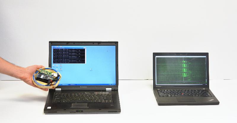
We demonstrate the extraction of secret decryption keys from laptop computers, by nonintrusively measuring electromagnetic emanations for a few seconds from a distance of 50 cm. The attack can be executed using cheap and readily-available equipment: a consumer-grade radio receiver or a Software Defined Radio USB dongle. The setup is compact and can operate untethered; it can be easily concealed, e.g., inside pita bread. Common laptops, and popular implementations of RSA and ElGamal encryptions, are vulnerable to this attack, including those that implement the decryption using modern exponentiation algorithms such as sliding-window, or even its side-channel resistant variant, fixed-window (m-ary) exponentiation.
We successfully extracted keys from laptops of various models running GnuPG (popular open source encryption software, implementing the OpenPGP standard), within a few seconds. The attack sends a few carefully-crafted ciphertexts, and when these are decrypted by the target computer, they trigger the occurrence of specially-structured values inside the decryption software. These special values cause observable fluctuations in the electromagnetic field surrounding the laptop, in a way that depends on the pattern of key bits (specifically, the key-bits window in the exponentiation routine). The secret key can be deduced from these fluctuations, through signal processing and cryptanalysis.

The attack can be mounted using various experimental setups:

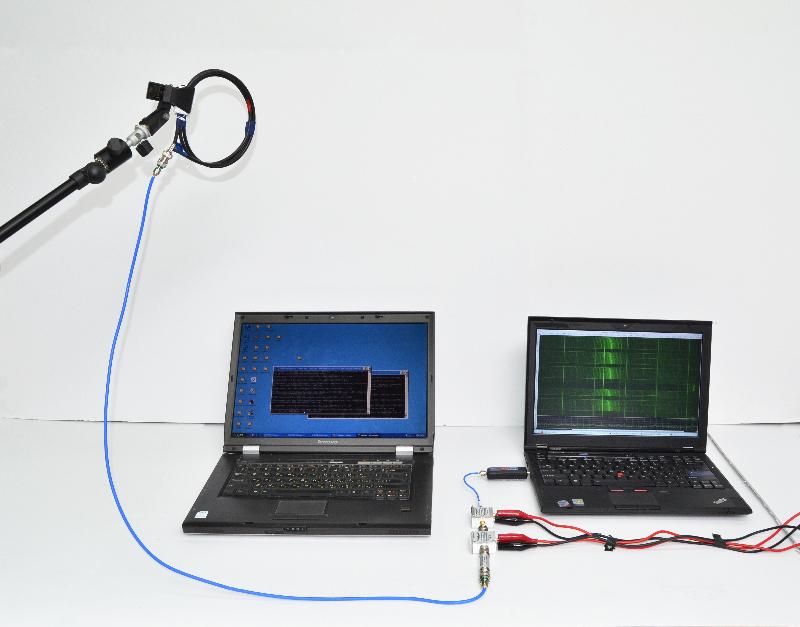
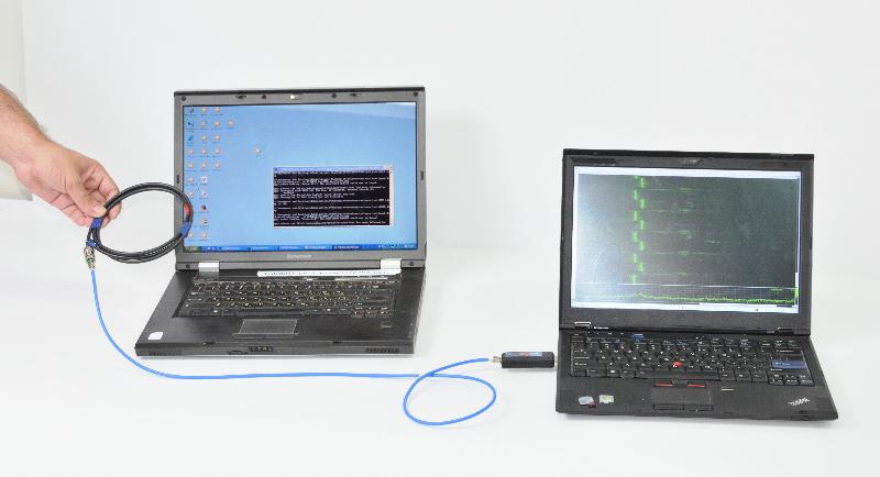
  • Software Defined Radio (SDR) attack. We constructed a simple shielded loop antenna (15 cm in diameter) using a coaxial cable. We then recorded the signal produced by the probe using an SDR receiver. The electromagnetic field, thus measured, is affected by ongoing computation, and our attacks exploit this to extract RSA and ElGamal keys, within a few seconds.
    Electromagnetic measurement
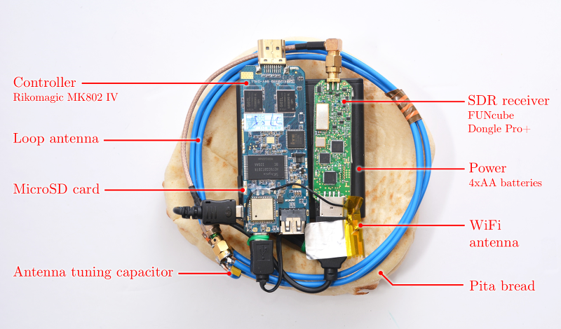
  • Untethered SDR attack. Setting out to simplify and shrink the analog and analog-to-digital portion of the measurement setup, we constructed the Portable Instrument for Trace Acquisition (Pita), which is built of readily-available electronics and food items (see instructions here). Pita can be operated in two modes. In online mode, it connects wirelessly to a nearby observation station via WiFi, and provides real-time streaming of the digitized signal. The live stream helps optimize probe placement and allows adaptive recalibration of the carrier frequency and SDR gain adjustments. In autonomous mode, Pita is configured to continuously measure the electromagnetic field around a designated carrier frequency, and records the digitized signal into an internal microSD card for later retrieval, by physical access or via WiFi. In both cases, signal analysis is done offline, on a workstation.
    Untethered Attack
  • Consumer radio attack. Despite its low price and compact size, assembly of the Pita device still requires the purchase of an SDR device. As discussed, the leakage signal is modulated around a carrier circa 1.7 MHz, located in the range of the commercial AM radio frequency band. We managed to use a plain consumer-grade radio receiver to acquire the desired signal, replacing the magnetic probe and SDR receiver. We then recorded the signal by connecting it to the microphone input of an HTC EVO 4G smartphone.
    radio attack

Q&A

Q1: What information is leaked by the electromagnetic emanations from computers?

This depends on the specific computer hardware. We have tested numerous laptop computers, and found the following:
  • In almost all machines, it is possible to tell, with sub-millisecond precision, whether the computer is idle or performing operations.
  • On many machines, it is moreover possible to distinguish different patterns of CPU operations and different programs.
  • Using GnuPG as our study case, we can, on some machines:
    • distinguish between the spectral signatures of different RSA secret keys (signing or decryption), and
    • fully extract decryption keys, by measuring the laptop's electromagnetic emanations during decryption of a chosen ciphertext.
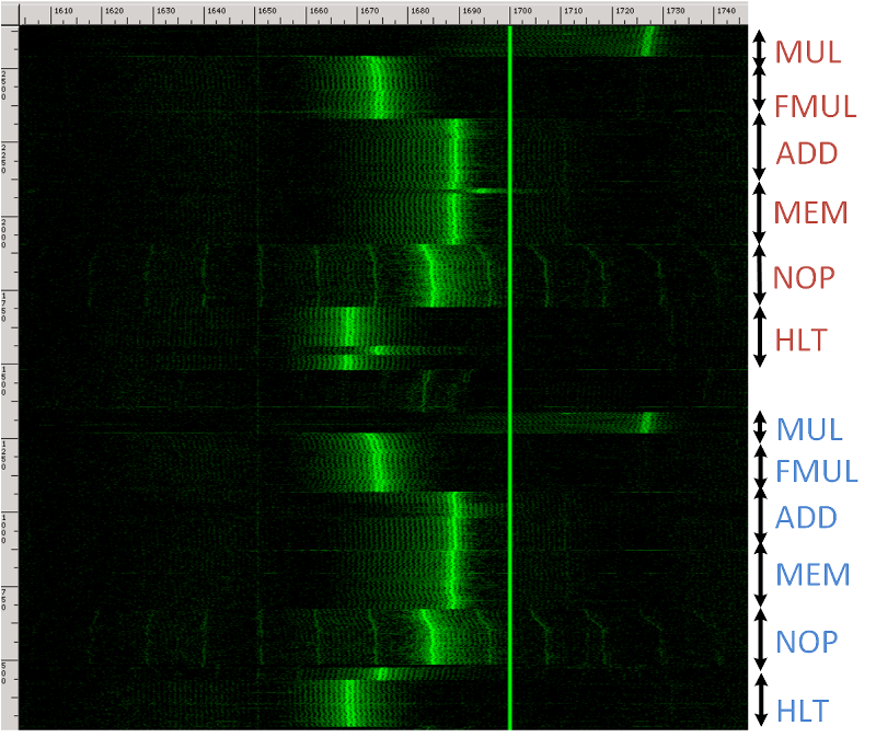
A good way to visualize the signal is as a spectrogram, which plots the measured power as a function of time and frequency. For example, in the following spectrogram (recorded using the first setup pictured above), time runs vertically (spanning 2.1 seconds) and frequency runs horizontally (spanning 1.6-1.75 MHz).  During this time, the CPU performs loops of different operations (multiplications, additions, memory accesses, etc.). One can easily discern when the CPU is performing each operation, due to the different spectral signatures.
various CPU operations

Q2: Why does this happen?

Different CPU operations have different power requirements. As different computations are performed during the decryption process, different electrical loads are placed on the voltage regulator that provides the processor with power. The regulator reacts to these varying loads, inadvertently producing electromagnetic radiation that propagates away from the laptop and can be picked up by a nearby observer. This radiation contains information regarding the CPU operations used in the decryption, which we use in our attack.

Q3: How can I construct such a setup?

  • Software Defined Radio (SDR) attack. The main component in the first setup is a FUNcube Dongle Pro+ SDR receiver. Numerous cheap alternatives exist, including ``rtl-sdr'' USB receivers based on the Realtek RTL2832U chip (originally intended for DVB-T television receivers) with a suitable tuner and upconverter; the Soft66RTL2 dongle is one such example.
  • Untethered SDR attack. The Pita device uses an unshielded loop antenna made of plain copper wire, wound into 3 turns of diameter 13 cm, with a tuning capacitor chosen to maximize sensitivity at 1.7 MHz (which is where the key-dependent leakage signal is present). These are connected to the aforementioned FUNcube Dongle Pro+ SDR receiver. We control the SDR receiver using a small embedded computer, the Rikomagic MK802 IV. This is an inexpensive Android TV dongle based on the Rockchip RK3188 ARM SoC. It supports USB host mode, WiFi and flash storage. We replaced the operating system with Debian Linux, in order to run our software, which operates the SDR receiver via USB and communicates via WiFi. Power is provided by 4 NiMH AA batteries, which suffice for several hours of operation.
    Pita Device
  • Consumer radio attack. We have tried many consumer-grade radio receivers and smartphones with various results. Best results were achieved using a "Road Master" brand consumer radio connected to the microphone jack of an HTC EVO 4G smartphone, sampling at 48 kHz, through an adapter cable. The dedicated line-in inputs of PCs and sound cards do not require such an adapter, and yield similar results.

Q4: What is the range of the attack?

In order to extend the attack range, we added a 50dB gain stage using a pair of inexpensive low-noise amplifiers (Mini-Circuits ZFL-500LN+ and ZFL-1000LN+ in series, 175$ total). We also added a low-pass filter before the amplifiers. With this enhanced setup, the attack can be mounted from 50 cm away. Using better antennas, amplifiers and digitizers, the range can be extended even further.
 long-range attack

Q5: What if I can't get physically close enough to the target computer?

There are still attacks that can be mounted from large distances.
  • Laptop-chassis potential, measured from the far end of virtually any shielded cable connected to the laptop (such as Ethernet, USB, HDMI and VGA cables) can be used for key-extraction, as we demonstrated in a paper presented at CHES'14.
  • Acoustic emanations (sound), measured via a microphone, can also be used to extract keys from a range of several meters, as we showed in a paper presented at CRYPTO'14.

Q6: What's new since your previous papers?

  • Cheap experimental setup. The previous papers required either a long attack time (about an hour) when using inexpensive equipment, or a fast attack (a few seconds) but using an expensive setup. In this paper we achieve the best of both, presenting an experimental setup which extracts keys quickly while remaining simple and cheap to construct.
  • New cryptographic technique addressing modern implementations. In the previous papers we attacked the naive square-and-multiply exponentiation algorithm and the square-and-always-multiply variant (which reduces side-channel leakage). However, most modern implementations utilize faster exponentiation algorithms: sliding-window, or for better side-channel resistance, m-ary exponentiation. In this paper we demonstrate a low-bandwidth attack on the latter two algorithms, extracting their secret keys.

Q7: How can low-frequency (kHz) leakage provide useful information about a much faster (GHz) computation?

We use two main techniques.
  1. Leakage self-amplification. Individual CPU operations are too fast for our measurement equipment to pick up, but long operations (e.g., modular exponentiation in RSA and ElGamal) can create a characteristic (and detectable) spectral signature over many milliseconds. Using a suitably chosen ciphertext, we are able to use the algorithm's own code to amplify its own key leakage, creating very drastic changes, detectable even by low-bandwidth means.
  2. Data-dependent leakage. While most implementations (such as GnuPG) attempt to decouple the secret key from the sequence of performed operations, the operands to these operations are key-dependent and often not fully randomized. The attacker can thus attempt to craft special inputs (e.g., ciphertexts to be decrypted) to the cryptographic algorithm that "poison" the intermediate values inside the algorithm, producing a distinct leakage pattern when used as operands during the algorithm's execution. Measuring leakage during such a poisoned execution can reveal in which operations the operands occurred, and thus leak secret-key information.

    For example, the figure presents the leakage signal (after suitable processing) of an ElGamal decryption. The signal appears to be mostly regular in shape, and each peak corresponds to a multiplication performed by GnuPG's exponentiation routine. However, an occasional "dip" (low peak) can be seen. These dips correspond to a multiplication by a poisoned value performed within the exponentiation routine. 

    signal example

Q8: How vulnerable is GnuPG now?

We have disclosed our attack to GnuPG developers under CVE-2014-3591, suggested suitable countermeasures, and worked with the developers to test them. GnuPG 1.4.19 and Libgcrypt 1.6.3 (which underlies GnuPG 2.x), containing these countermeasures and resistant to the key-extraction attack described here, were released concurrently with the first public posting of these results.

Q9: How vulnerable are other algorithms and cryptographic implementations?

This is an open research question. Our attack requires careful cryptographic analysis of the implementation, which so far has been conducted only for the GnuPG 1.x implementation of RSA and ElGamal. Implementations using ciphertext blinding (a common side-channel countermeasure) appear less vulnerable.

Q10: Is there a realistic way to perform a chosen-ciphertext attack on GnuPG?

GnuPG is often invoked to decrypt externally-controlled inputs, fed into it by numerous frontends, via emails, files, chat and web pages. The list of GnuPG frontends contains dozens of such applications, each of them can be potentially used in order to make the target decrypt the chosen ciphertexts required by our attack. As a concrete example, Enigmail (a popular plugin to the Thunderbird e-mail client) automatically decrypts incoming e-mail (for notification purposes) using GnuPG. An attacker can e-mail suitably-crafted messages to the victims (using the OpenPGP and PGP/MIME protocols), wait until they reach the target computer, and observe the target's EM emanations during their decryption (as shown above), thereby closing the attack loop. We have empirically verified that such an injection method does not have any noticeable effect on the leakage signal produced by the target laptop. GnuPG's Outlook plugin, GpgOL also did not seem to alter the target's leakage signal.

Q11: What countermeasures are available?

Physical mitigation techniques of electromagnetic radiation include Faraday cages. However, inexpensive protection of consumer-grade PCs appears difficult. Alternatively, the cryptographic software can be changed, and algorithmic techniques employed to render the emanations less useful to the attacker. These techniques ensure that the rough-scale behavior of the algorithm is independent of the inputs it receives; they usually carry some performance penalty, but are often used in any case to thwart other side-channel attacks. This is what we helped implement in GnuPG (see Q8).

Q12: Why software countermeasures? Isn't it the hardware's responsibility to avoid physical leakage?

It is tempting to enforce proper layering and decree that preventing physical leakage is the responsibility of the physical hardware. Unfortunately, such low-level leakage prevention is often impractical due to the very bad cost vs. security tradeoff: (1) any leakage remnants can often be amplified by suitable manipulation at the higher levels, as we indeed do in our chosen-ciphertext attack; (2) low-level mechanisms try to protect all computation, even though most of it is insensitive or does not induce easily-exploitable leakage; and (3) leakage is often an inevitable side effect of essential performance-enhancing mechanisms (e.g., consider cache attacks).

Application-layer, algorithm-specific mitigation, in contrast, prevents the (inevitably) leaked signal from bearing any useful information. It is often cheap and effective, and most cryptographic software (including GnuPG and libgcrypt) already includes various sorts of mitigation, both through explicit code and through choice of algorithms. In fact, the side-channel resistance of software implementations is nowadays a major concern in the choice of cryptographic primitives, and was an explicit evaluation criterion in NIST's AES and SHA-3 competitions.

Q13: What does the RSA leakage look like?

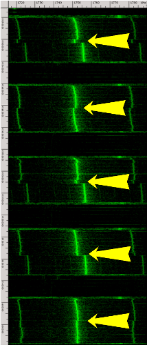
Here is an example of a spectrogram (which plots the measured power as a function of time and frequency) for a recording of GnuPG decrypting the same ciphertext using different randomly generated RSA keys:

spectrogram of multiple GnuPG RSA decryptions

In this spectrogram, the horizontal axis (frequency) spans ranges from 1.72 MHz to 1.78 MHz, and the vertical axis (time) spans 1.2 seconds. Each yellow arrow points to the middle of a GnuPG RSA decryption. It is easy to see where each decryption starts and ends. Notice the change in the middle of each decryption operation, spanning several frequency bands. This is because, internally, each GnuPG RSA decryption first exponentiates modulo the secret prime p and then modulo the secret prime q, and we can actually see the difference between these stages. Moreover, each of these pairs looks different because each decryption uses a different key. So in this example, by simply observing electromagnetic emanations during decryption operations, using the setup from this figure, we can distinguish between different secret keys.

Q14: What is the difference between your attack and the recent cache attack by Yarom et al.?

Cache side channel (timing cross-talk between processes or virtual machines) apply to scenarios where the attacker can execute code on the same physical machine as the targeted process (e.g., in shared computers, such as Infrastructure as a Service cloud computing).

Our attack exploits physical information leakage from computation devices, and does not require the attacker to execute his own code on the intended target.


Acknowledgments


Tuesday, June 16, 2015

EXPLOSIVES TEXTILES

welcome back to war! Today's subject as I already said yesterday explosive textiles:
"Rayon is a fiber produced from recycled wood pulp or bamboo cellulose processed by a combination of many chemicals involving carbon disulphide, sulfuric acid, ammonia, acetone and caustic soda to bear regular washing and constant wearing"
"Acrylic’s manufacturing process, if not properly monitored can result in an explosion. Acrylic fibers are highly inflammable and not easy recyclable nor biodegradable in the environment. "


ITS NEED AN ORGANIC SOLVENT:
2-Butanol, or sec-butanol, is an organic compound with formula CH3CH(OH)CH2CH3. This secondary alcohol is a flammable, colorless liquid that is soluble in 3 parts water and completely miscible with polar organic solvents such as ethers and other alcohols. It is produced on a large scale, primarily as a precursor to the industrial solvent methyl ethyl ketone. 2-Butanol is chiral and thus can be obtained as either of two stereoisomers designated as (R)-(−)-2-butanol and (S)-(+)-2-butanol. It is normally found as an equal mixture of the two stereoisomers — a racemic mixture

precision solvent cleaners, which are mixtures of various hydrocarbon solvents

Saturday, June 13, 2015

RF Safe-Stop Shuts Down Car Engines With Radio Pulse

An anonymous reader writes with news of a device built by a company in the U.K. which uses pulses of electromagnetic energy to disrupt the electronic systems of modern cars, causing them to shut down and cut the engine. Here's a description of how it works: "At one end of a disused runway, E2V assembled a varied collection of second-hand cars and motorbikes in order to test the prototype against a range of vehicles. In demonstrations seen by the BBC a car drove towards the device at about 15mph (24km/h). As the vehicle entered the range of the RF Safe-stop, its dashboard warning lights and dials behaved erratically, the engine stopped and the car rolled gently to a halt. Digital audio and video recording devices in the vehicle were also affected.''It's a small radar transmitter,' said Andy Wood, product manager for the machine. 'The RF [radio frequency] is pulsed from the unit just as it would be in radar, it couples into the wiring in the car and that disrupts and confuses the electronics in the car causing the engine to stall.'

http://news.slashdot.org/story/13/12/03/1919230/rf-safe-stop-shuts-down-car-engines-with-radio-pulse

Where to Buy :

guided wave radar transmitter :)
http://dir.indiamart.com/impcat/radar-level-transmitter.HTML


Wednesday, June 10, 2015

Tuesday, June 9, 2015

Defense Distributed: Successful test fire of first 3D printed pistol (video)

Defense Distributed has released a video of the successful test firing by hand of their first complete 3D printed pistol, the "Liberator". The Liberator has only one metal part, the firing pin, made from a common nail. In the video, Cody Wilson is shown firing the pistol by hand, to dramatically illustrate his faith in the design. The Liberator is a single shot pistol in .380 (9X17) caliber. While firearms have been made in home workshops ever since they have been in existence, the ability to download computer files and have a computer controlled machine print all the parts to a functioning firearm has caught the public attention.  Dean Weingarten, Defense Distributed Distributor

1 comment:

Scotty said...
A metal detector could sense the steel firing pin nail and/or the bullet itself if set to high sensitivity. The entire weapon would be detected by most other types of body scanners. The point is - it's not guaranteed to make it through the current screening technology. As for legality, all existing gun ownership laws would still apply. For instance: If you print and assemble one in Massachusetts without a license, background check, and required training, you will be arrested if caught with it in your home or possession. The gun's printed material cannot withstand the heat and wear of repeated firing, particularly with more powerful rounds where chamber pressures may exceed 35,000 psi. Rifling, necessary for accuracy at more than a few yards, is not feasible and will disappear after the first few firings. (if not the first) Finally, if you want a durable gun and are not willing to get it legally, well, just ask a bank robber how it's done. But if you're willing or able to secure whatever permit your state requires, then pick up a used pistol at the local gun store for a quarter the cost of a printer. I'm as disgusted by the over-reaching nature of the federal government as most gun owners, but really - this is not the answer
http://gunwatch.blogspot.pt/2013/05/defense-distributed-successful-test.HTML

$1200: The price of (legally) 3D printing your own metal AR-15 rifle at home

 
Metal Gun

Share This article

1.8K74187
Defense Distributed has made a habit of provoking government regulators in its quest to bring 3D-printed firearms to home hobbyists. The most recent loophole exploited by Defense Distributed is once again about creating a working firearm at home, but unlike the 3D-printed Liberator pistol, this one isn’t made of plastic. The Ghost Gunner is a small CNC milling machine that costs a mere $1200 and is capable of spitting out an aluminum lower receiver for an AR-15 rifle. This device allows people with no gunsmith training to assemble a working assault rifle at home with no licensing or serial number — and it’s completely legal.
The Ghost Gunner itself is a small box about one foot on each side. Inside is an Arduino controller and a custom-designed spindle that holds a steel carbide drill bit. It works like any other CNC machine — the drill spins up and moves in three dimensions to carve items out of blocks of metal. However, this machine is specifically intended to make an AR-15 lower receiver. That’s the part of a gun that connects the stock, barrel, and magazine. You could say it’s the “gun” part of a gun. It’s also the part that’s regulated by the ATF and assigned a serial number. Selling it without a license is illegal, but making it yourself is perfectly fine. An untraceable gun built without a serial number is often called a “ghost gun” by gun control advocates, so of course Defense Distributed borrowed the term to ruffle feathers.

Ghost Gunner
The Ghost Gunner. Slide in a block of aluminum — and out comes a printed AR-15 lower receiver.
This is only the latest example of Defense Distributed pushing the bounds of home manufacturing technology to make a point. The organization is run by founder Cody Wilson, who isn’t shy about explaining his radically libertarian ideals. Allowing everyone to create an assault rifle with a few clicks is his way of showing that technology can always evade regulation and render the state obsolete. If a few people are shot by ghost guns, that’s just the price we have to pay for freedom, according to Wilson.
3D printing guns like the Liberator was more of a statement — it showed that a new era of manufacturing tech is upon us. Of course, no one would ever want to use a plastic gun if given the choice. The Liberator is prone to failure (video below), and usually only manages a few poorly aimed shots. In designing a cheap CNC machine specifically to make gun parts, Defense Distributed is delivering a viable weapon (other CNC mills cost many thousands of dollars). If you can make a lower receiver, all the other parts can be ordered online cheaply and legally.

The Ghost Gunner is capable of making anything that fits in the build envelope, as long as it’s created with Defense Distributed’s Physibles Development SDK (pDev) and distributed as a .dd file. In that respect, it’s not much different than any number of 3D printers. This is an entirely new era in the manufacturing of real world objects, in both plastic and metal. It used to be that you needed training as a gunsmith to make your own firearm, but that’s no longer the case. Whether or not you agree with Defense Distributed on the value of untraceable firearms in a free society, this is happening and regulation is miles behind the technological curve.
http://www.extremetech.com/extreme/191388-1200-the-price-of-legally-3d-printing-your-own-metal-ar-15-rifle-at-home

Fadal VMC4020 CNC Vertical Machining Center Milling Machine 3 Axis

Friday, June 5, 2015

NON DETECTABLE GLOCK 7

welcome back to war! Today's subject, ceramic guns non detectable! Ok, everybody knows here I've been trought the Glock 7, everybody wants to ge the hands on smile emoticon Now, we already have a 3D design for a Glock piece, but we didn't have teh right material, which the Glock 7 is made of, so here it is:

Making Cermet II Materials
What follows are some explanations of how to make advanced carbide.  These are pretty short explanations but they will give an idea of all that is possible. 
Obviously we use different techniques for different grades and applications.  We have compiled a great deal of infomation on Carbide and Advanced Materials in our Tool Tipping Index.  
How It Works 
Carbide wear is due to micro-fracturing, macro-fracturing, grain pull out, corrosion of the binder, adhesion between the carbide and the material being cut, and tribological functions which are similar to a naturally occurring electro-etching. 
Cermet II technology uses a variety of carbides such a titanium carbide, tungsten carbide, Tantalum carbide, Niobium carbide and others.  Steel is iron with a very small amount of carbide but it is very different than plain iron.  The addition of a very small amount of the right material can make a huge difference in carbide performance as well. 
Cermet II grades also use unique binder formulations.  Cobalt is a good binder material and is used in standard grades.  It was the first binder used and is still easiest to use.  However cobalt is pure metal and is subject to chemical attack.  Part of the secret of our Cermet II grades is to chemically alloy special binders with a proprietary metalloid which makes the cobalt binder non-reactive so it doesn’t corrode.  It also greatly strengthens the binder so grinds aren’t pulled out. 
Cermet II grades have special binder properties so that they behave more as a solid piece of material than as a cemented piece of material.  Think of a steel alloy as compared to concrete.  
Grain Size 
The most important reason for this widening of the spectrum of available WC grades is that, besides those variations achieved by cobalt contents and some carbide additives, the properties of WC-Co hardmetals such as hardness, toughness, strength, modulus of elasticity, abrasion resistance and thermal conductivity can be widely varied by means of the WC grain size. While the spectrum of available WC grain sizes ranged from 2.0 to 5.0 µm in the early days of the hardmetal industry in the mid 1920’s, the grain sizes of WC powders now used in hardmetals range from 0.15 µm to 50 µm, or even 150 µm for some very special applications.  
Grain Size 
The history of tungsten carbide powder metallurgy, and especially that of the hardmetal industry, is characterized by a steadily widening range of available grain sizes for processing in the industry; while, at the same time, the grain size distribution for each grade of WC powder became narrower and narrower. 
The most important reason for this widening of the spectrum of available WC grades is that, besides those variations achieved by cobalt contents and some carbide additives, the properties of WC-Co hardmetals such as hardness, toughness, strength, abrasion resistance and thermal conductivity can be widely varied by means of the WC grain size. While the spectrum of available WC grain sizes ranged from 2.0 to 5.0 µm in the early days of the hardmetal industry in the mid 1920’s, the grain sizes of WC powders now used in hardmetals range from 0.5 µm to 50 µm, or even 150 µm for some very special applications. 
The first submicron hardmetals were launched on the market in the late 1970s and, since this time, the micro-structures of such hardmetals have become finer and finer. The main interest in hardmetals with such finer grain sizes derives from the understanding that hardness and wear resistance increase with decreasing WC grain size. 
With optimum grade selection, sub micron grain size tungsten carbide can be sharpened to a razor edge without the inherent brittleness frequently associated with conventional carbide. Although not as shock-resistant as steel, carbide is extremely wear-resistant, with hardness equivalent to Rc 75-80. Blade life of at least 50X conventional blade steels can be expected if chipping and breakage is avoided. 
Advanced Manufacturing Techniques 
Better, cleaner powder has been achieved through improved solvent extraction in tungsten chemistry as well as new techniques in hydrogen reduction and carburization to improve the purity and uniformity of tungsten and tungsten carbide powder. 
New powder milling, spray drying and sintering techniques have resulted in improved hardmetal properties and performance. Notably, the continuous improvement of vacuum sintering technology and, starting from the late 1980’s, hot isostatic pressure sintering (SinterHIP) led to new standards in hardmetal quality. 
http://www.carbideprocessors.com/pages/carbide-parts/making-cermet-material.html

Tuesday, June 2, 2015


The design for thermonuclear ignition that Klaus Fuchs turned over to his Soviet control in March 1948. The detonator (box) on the left represents a gun-type fission bomb consisting of a projectile and target of highly enriched uranium (71 kg of 70% pure U235), which when joined form a supercritical mass and produce an explosive chain reaction. The projectile is carried forward by its momentum, striking the beryllium-oxide (BeO) capsule on the right, which contains a liquid 5...0:50 D–T mixture, compressing it by a factor of about 3, as represented by the outer circle. The radiation produced in the fission bomb heats up the BeO capsule, producing completely ionized BeO gas, which exerts pressure on the completely ionized D–T gas, compressing the capsule further to an overall factor of about 10, as represented by the inner circle.
The detonator is а fission bomb of the gun type. The active material is 71 kg of 40% pure U233 [sic].3 The plug (48.64 kg) sits in the projectile, which is shot bу the gun into the target, the remaining 22-24 kg sits in the target. The tamper is ВеО. The fission gadget has аn efficiency of 5% (calculated). The tamper, which is transparent for the radiation from the fission bomb, is surrounded bу an opaque shell which retains the radiation in the tamper and also shields the booster and main charge against radiation. […]
The primer contains 346 gm of liquid D-Т in 50:50 mixture, situated in the tamper. It is first compressed bу the projectile to 3-fold density. This precompression may not bе necessary. As the tamper and primer аге heated bу the radiation, the primer is further compressed, possibly to 10-fold density. (Radiation transport equalises the temperature in primer and tamper, and gives therefore rise to а pressure differential.) The compression opens the “gap” for the ignition of the primer. The primer is likely to have а very high efficiency (~80 %) of energy release.
The booster beyond the radiation shield contains D with about 4% Т. It is ignited bу the neutrons from the primer. Beyond the booster is the main charge of pure D, а cylinder of about 30 сm radius to contain the neutrons and arbitrary length.

So what’s happening here is that the big piece of uranium is being shot against another piece

and this is how to stabilize the spheres, Van Graaf generator  

Sunday, May 31, 2015

Silica Aerogel (TEOS, Base-Catalyzed)


Editor’s Note: This is an adaptation of the silica aerogel procedure from the Lawrence Berkeley National Laboratory site about aerogels, which for a long time was the only procedure for making aerogels publicly available. That procedure, we’re sorry to say, does not work. Maybe you’ve tried it. If you have, you’ll have noticed that the solution stays separated as two layers and a gel never forms. That’s because there’s not enough alcohol. Maybe it was a typo. So we modified that procedure and present the modified version that works for us below.  If for some reason you have trouble with the procedure below, please leave a comment!

Materials

  • Tetraethoxysilane (tetraethyl orthosilicate), Si(OC2H5)4
  • Absolute (200-proof) ethanol
  • Deionized water
  • Ammonium hydroxide, 28-30 wt % in water
  • Ammonium fluoride, NH4F
Optional
  • Acetone

Gel Preparation

An Excel calculator for determining amounts of chemicals required by target volume (mL) or mass (g) is available.
  1. Weigh 1.852 g NH4F and add it to 100 mL of water. Add 20.50 g (22.78 mL) ammonium hydroxide solution. Store this in a bottle so you can reuse it later. This is the “ammonium fluoride/ammonium hydroxide stock solution”. If you already have stock solution prepared you can skip down to step 2.
  2. Mix 4.7 g (5.0 mL) TEOS and 8.68 g (11.0 mL) ethanol in a beaker. This is the “alkoxide solution”.
  3. Mix 7.0 g (7.0 mL) water and 8.68 g (11.0 mL) ethanol in another beaker. Add 0.364 g (0.371 mL, ~8-10 drops from a disposable pipette) of ammonium fluoride/ammonium hydroxide stock solution. This mixture is the “catalyst solution”.
  4. Pour the catalyst solution into the alkoxide solution and stir. This is the “sol”.
  5. Pour the sol into molds and allow gel to form. Gel time is approximately 8-15 min.

What Everything Does

TEOS is the source of the silica. Water is what hydrolyzes the TEOS so that it can polymerize. Ethanol is a co-solvent that is miscible with both TEOS and water to get both into the same phase so they can react. Ammonium hydroxide is a basic (alkaline) catalyst that helps to make the reactions go faster. Fluoride ion is a catalyst that helps hydrolysis happen more quickly.

What Doesn’t Work

  • Not using ammonium fluoride. It actually makes a big difference with TEOS. Although fluoride also makes reactions with TMOS go faster, TMOS will work fine with just a basic catalyst without fluoride.
  • Using denatured alcohol that contains anything other than methanol or isopropanol as a denaturant instead of absolute ethanol. Some hardware store alcohol works, some doesn’t.
  • Using sodium hydroxide (NaOH) instead of ammonium hydroxide in equal molar concentration. NaOH is a strong base so if you use it you’ll need to use a lower molar concentration of it than for ammonium hydroxide.

Variables You Can Play With

  • Try adjusting the amount of solvent used to adjust the density of the resulting aerogel.
  • Try adjusting the amount of the catalysts in the stock solution or the amount of stock solution you add. This will change the gel time and possibly the clarity of the gel (more catalyst means faster gel time but possibly lower transparency).
  • You can substitute sodium hydroxide, sodium carbonate, or potassium carbonate for ammonium hydroxide but you will have to experiment with the amount.
  • You can substitute sodium fluoride for ammonium fluoride in equal molar concentration, although your gel time may be affected since you lose the buffering effect of the extra ammonium ions.

Gel Processing Conditions

  1. Once the gel has set, place it under ethanol and allow the gel to age for at least 24 h.
  2. Exchange into 200-proof ethanol or acetone at least four times over the course of several days to a week.
  3. Supercritically dry. A suggested procedure would be to heat the CO2 through its critical point (31.1°C and 72.9 bars) to ~45°C while maintaining a pressure of ~100 bars. Depressurize at a rate of ~7 bar h-1.

What You Should Get

A transparent silica aerogel with a blue cast from Rayleigh scattering that appears yellowish when viewed in front of a light source from Mie scattering.
  • Density 0.040 g cm-3
  • Surface area 700 m2 g-1

Useful Information

Tetraethoxysilane (tetraethyl orthosilicate):
  • Molecular weight 208.33 g mol-1
  • Density 0.933 g mL-1
  • Smells a little bit like spearmint
  • Sigma-Aldrich part number 131903
Ethanol:
  • Molecular weight 46.07 g mol-1
  • Density 0.789 g mL-1
  • Sigma-Aldrich part number 459836 or 459844, or get Everclear from a liquor store
Ammonium fluoride:
  • Molecular weight 37.04 g mol-1
  • Form is a fluffy, lightweight solid
  • Sigma-Aldrich part number 216011
Ammonium hydroxide:
  • Concentration is 28-30 wt % in water typically
  • Molecular weight of NH4OH is 35.05 g mol-1, but this is not the molecular weight of the solution
  • Density 0.9 g mL-1
  • Form is a pungent liquid that smells like cleaning ammonia, use in a vent hood
  • Sigma-Aldrich part number 221228
http://www.aerogel.org/?p=1027
Thursday, May 28, 2015

DIRTY BOMB - X RAY POWDER

So, today I finally reached a fantastic conclusion: any microcrystalline powder substance, which can be exposure to an x ray machine, can get so many radioactivity tha might be used for any dirty bomb. That opens the possibility of anyone can build the bomb. For any good dirty bomb its needed at least 500 microcuries, and that its possible to achieve with 100 gr of powder.

X-ray powder photograph A photograph produced by monochromatic X-irradiation of a sample of microcrystalline powder placed at the centre of a circular camera, e.g. a Debye-Scherrer camera. Diffracted X-rays are recorded on a strip of film wrapped around the circumference of the camera. The angular position of the diffracted X-rays on the film gives structural information about the sample. See also X-RAY DIFFRACTION CRYSTALLOGRAPHY

Monday, May 25, 2015


Search Results : nuclear light bulb » The Unwanted Blog

Jul122012
 
Cyanotype Print 01: Nuclear Light Bulb
A NASA diagram of a Nuclear Light Bulb, an advanced nuclear rocket that uses incandescent uranium plasma to irradiate hydrogen gas to provide thrust. NOTE: There is a mis-spelled word on the blueprint. It was mis-spelled by NASA way back when… it’s shown as it was published.

A hand made cyanotype blueprint on sturdy 12X18 watercolor paper. Each is unique, and likely to feature small imperfections.The blue will fade if left in the sun. If this happens, it can be darkened by placing it somewhere dark with good air flow to re-oxidize the ink. Alternatively. hydrogen peroxide, available from grocery stores, will instantly oxidize the ink and restore it to its full hue.
 Posted by at 7:50 pm
Jul282010
 
To continue
A uranium plasma with a core temperature of 42,000 degrees Rankine (23,333 K) is simply incapable of being held by any solid structure. The highest melting point of any known substance is tantalum hafnium carbide, at 4488 K. The uranium plasma would simply evaporate any material it came into contact with.
So, the trick was to make sure the uranium plasma didn’t come into contact with any solid materials. To do this, a “radial inflow vortex” was to be employed. Within the cylindrical reactor chambers, the uranium plasma would be held within the center, away from direct contact with the walls, by a rapidly rotating sheath of neon gas. Injected tangentially along the walls, the neon gas would travel in a helical pattern up the length of the cylinder and would be extracted at the forward end, to be cooled and recycled back into the system. The rapid rotation of the neon gas would be translated to the uranium plasma, and the whole plug of gas would spin at a high rate. Centrifugal force would keep the system properly distributed… while normally it would seem that a uranium gas would be denser than neon, the fact was that at the fabulously high temperatures involved, the uranium would be lower density than the cooler neon, and thus would be suspended in the core, away from the walls.
While the core temperature of the uranium plasma was 42,000 R, the outer surface would be a comparatively chilly 15,000 R. This is of course still far in excess of what any material structure can handle. But the neon, already a gas, could handle 15,000 R; due to the vortext structure, the innermost surface of the neon layer, where it was in contact with the uranium, would also be at 15,000 R, but a steep temperature gradient dropped the temperature to a modest, and structurally possible, temperature of 2000 R at the walls. The thickness of the neon gas layer was estimated to be under 0.05 feet.
Each of the seven chambers would have a neon flow rate of 2.96 pounds per second, and an axial velocity of 1.95 feet per second and a tangential velocity of 10 feet per second, with a total dwell time of 3.8 seconds. The hot neon would extract energy from the reactor, of course, to the sum of 4,120 BTU/sec. The hot neon would be used, in part, to pre-warm the hydrogen fuel.
—————–
nlb1.jpg
Schematic view of one of the seven chambers in the nuclear lightbulb engine (United Aircraft)
————–
Even with the neon buffer layer, a simple glass wall would not be sufficient to withstand the harsh environment. As well as simply being in contact with 2000 R neon gas, the transparent wall would also have a vast sleet of radiation passing through it… infra-red, gamma rays, neutrons, the whole spectrum. Once again there was the problem that no transparent material would possibly be able to survive the environment. Even the most optically transparent material will absorb some of the radiation passing through it… and this absorbed energy will be converted directly to heat. It would not take very long at all for the clearest substance to get incredibly hot… which, of course, was the goal with the hydrogen propellant. What was desired for the propellant was manifestly not desired for the structure.
So the transparent walls were to be made not out of monolithic sheets, but thin-walled tubes. High-purity fused silica was the baselined material of choice. Thought was given to single-crystal beryllium oxide and synthetic quartz as materials, as they had better transparency in the ultraviolet, but production of the required tubes using these materials was undemonstrated. To cool the tubes, hydrogen gas would be pumped through.
The cylindrical walls were built in three 120-degree radial segments. At the end of each segment was a manifold for injection or extraction of the hydrogen coolant, so the hydrogen did not travel very far around the circumference of the cylinder. This assured that the hydrogen did not have time to heat up to much, and that the silica glass would be maintained at a reasonably constant temperature of between 800 and 1100 Celcius (yes, the reports have units all over the place). Corning Type 7940 and General Electric Type 151 fused silicas typically had a purity of SiO2 of 99.997 percent, with Al2O3 being the primary impurity. Purity was essential… the greater the purity, the greater the transparency.
Since this was the late 1960’s, United Aircraft actually ran a number of physical experiments to demonstrate the feasibility of their designs and materials, rather than a series of colorful computer simulations. As operating a uranium plasma reaction was somewhat beyond the scope and funding of their contract with NASA, they instead used a 1.2 megawatt RF induction heater to generate an argon plasma of about 15,000 R in a subscale “reactor.” The subscale test setup used both axial tubes (with wall thicknesses down to 0.005inches) and circumferential tubes potted into the manifold with RTV silicone.
———–
nlb8.jpg
Schematic view of test setup (United Aircraft)
————–
nlb6.jpg
Test setup with annular tubing (United Aircraft)
————
nlb9.jpg
Details of test hardware (United Aircraft)
——————–
In the tests, water rather than hydrogen was used as the coolant.
Test results were generally encouraging, but a number of issues were discovered. One of the more odd things that was noted in this and other testing was that the color of the glass tubes was a variable during the course of nuclear engine operation. Radiation damage to the glass would cause the glass to gradually become blue, then purple, then black. This is, of course, fatal to not only the functioning of the engine, but the survivability of the glass. Any amount of coloring would cause massive increase in radiation absorbtion, resulting in rapid overheating and structural failure. But over 800 Celcius, the  glass would thermally anneal… which would wipe out the coloration and restore transparency. Thus the need to keep the glass operating at a minimum of 800 C. But above 1100 C, devitrification of the glass would occur… it would continue to be perfectly servicable clear glass, but once it began to cool down after engine shutdown the surface of the glass would turn milky white due to a myriad of microscopic surface cracks. This would cause the glass to overheat if the engine was restarted. And thus the need to make sure that the glass did not rise above 1100 C.
————–
nlb2.jpg  nlb3.jpg  nlb4.jpg  nlb5.jpg  nlb7.jpg
Photos of test hardware (United Aircraft)
______________
To Be Continued…
 Posted by at 5:02 pm
Jul172010
 
The operating principle of the Nuclear Lightbulb is simple: a self-sustaining uranium plasma would be contained within a glass vessel; radiant energy would pass through the “bulb” and heat hydrogen gas surrounding it, which in turn would be contained within a metal chamber. The superheated gas would then pass through a nozzle and generate thrust in the normal fashion.
While simple to describe, almost nothin about this was simple to design. The engineering involved would have been monumental. And while the Nuclear Lightbulb is typically described in simple terms and illustrated with simple sketches, it turns out that a lot of work was done on this engine concept, (seemingly) mostly by the United Aircraft Corporation. The United Tech Research Lab produced a fairly detailed design for a reference engine, and did much more work – including many physical experiments – on the componant designs than is generally known. The reference engine had seven separate “bulbs,” each a cylinder 6 feet long by 2.3 feet in diameter. The engine operated at 500 atmospheres pressure.
First off, the uranium plasma. Generating the plasma would be fairly straightforward… simply get enough of the right fissile material into an enclosed volume of the right size, and nuclear chain reactions will do the job. In this case, a critical mass of 34.7 pounds of Uranium 233 spread between the seven chambers would cause the uranium to melt, vaporize and finally become a plasma.
Step one in the process would be to actually gather that much U233 within the chambers. Obviously it could not be stored as a solid block, but instead scattered and diffuse so that nuclear reactions would not begin until it was in the reactor. In order to accomplish this, three methods were proposed:
1) Store the uranium in the form of uranium hexafluoride (UF6). The UF6 gas would be simply pumped or injected into the reactors like any other gas. Storage of the UF6 was not described, but it probably would have involved very large tanks of very low pressure (and thus low density) filled with a neutron absorbing foam. As the UF6 began to gather under increasing pressure and density, nuclear reactions would begin to take hold and the temperature would increase. At a pressure of 200 psi, the UF6 would totaly dissociate by 13,000 degrees Rankine, allowing the fluorine to be drawn off from the Uranium. The problem, of course, is that the byproduct would be fluorine gas at about 13,000 degrees Rankine. Fluorine is trouble enough at room temperature. While the gas would be cooled prior to contact with any solid structural material, fluorine that can be described in any way as “hot” is a terrifying notion.
2) Inject molten uranium. This, however, would require some means to melt the uranium, as well as inject it. The melting temperature of uranium is 1403 degrees Kelvin; while this is by no means impossibly hot to work with (metals such as tungsten and many ceramics have melting points far higher), it would still be a complication. While the plan was that the molten uranium would be injected into the reactor in the form of an aerosol suspended within a high temperature carrier gas such as neon, it was expected that the uranium would plate on the mechanical portions of the injector system.
3) A third option was similar to the molten uranium aerosol, but with the temperature lowered so that the uranium was still a solid. Here the uranium would be divided into an extremely fine dust… pumpable, injectable, would not plate out onto the structural surfaces. As the dust begins to build up within the reactor, nuclear chain reactions would cause it to heat, eventually becoming a plasma. Once the full critical mass was injected into the reactor and the system reached equilibrium, the plasma would reach an average temperature of 42,000 degrees Rankine (23,333 Kelvin). This superheated plasma would glow fiercely, providing the radiant energy needed to superheat the hydrogen propellant. But there is no material known, certainly no transparent material, that can withstand anything remotely like the temperature of the uranium plasma. A solution to containment, however, was found.
To be continued…
 Posted by at 10:12 am
Jul102010
 
The NERVA nuclear rocket used a sorta-conventional nuclear reactor as its basis. As the reactor was brought up to power, the solid fuel elements would heat up; hydrogen would be sent through coolant channels. The hydrogen would of course heat up, cooling the reactor. When operated properly, the temperature in the reactor would reach a steady state; a temperature limited by the structural capabilities of the solid reactor materials.
The hotter the reactor, the hotter the hydrogen, and the better the rocket performance. However, the hotter it gets, the softer the reactor structural elements get; at some point it fails structurally, and perhaps even melts. So the temperature must be limited. And the temperature limits limit performance. NERVA was quite cool compared to the combustion temperature of a conventional hydrogen/oxygen rocket engine. However, the extremely low molecular weight of the pure hydrogen exhaust compared to the H2O exhaust of the chemical rocket makes up for that, providing about twice the specific impulse.
In order to greatly improve specific impulse, the temperature of the hydrogen must be increased; and to do that the temperature of the reactor must be increased. It quickly becomes impossible to have a solid-core reactor, and one must accept that the uranium will not be a solid. So rocket designers of the early 1960’s came up with the liquid-core nuclear rocket, with molten uranium; and then the gas-core rocket where the uranium is so hot it has actually vaporized. But the problem was containing the uranium. Typically centrifugal force (by spinning the rocket around its central axis) was employed; the uranium liquid or gas would, hopefully, be stuck to the outer wall of the rocket reaction chamber, while lighter hydrogen would migrate to the core, and then out the nozzle. The thickness of the uranium liquid or gas would be less than the distance from the chamber wall inwards to the nozzle, so the hope was that ther uranium wouldn’t be able to flow out the nozzle. A simple idea made extremely difficult in actual practice… massive, extremely hot nuclear reactors being spun at high rate around their central axis, with little to no vibration while being injected with liquid hydrogen? Not exactly the description of a straightforward engineering problem. With all the effort involved, uranium was still expected to leak out the nozzle, making the propulsion system both filthy (a minor concern in deep space) and wasteful of uranium (a serious concern).
Another solution was devised in the mid 1960’s that in principle would combine the best of both worlds… uranium brought up to plasma temperatures, and uranium contained physically so that it could not escape. This concept was known as the Nuclear Light Bulb.
TO BE CONTINUED…

       
 Posted by at 2:44 pm
May152013
 
I’ve made many test runs and made considerable progress. I’ve also run out of supplies and need to improve the mechanical infrastructure. so I’ve decided to sell the “prototypes” I’ve made. These are indeed  prototypes, and more to the point they are prototypes of art, so they are imperfect and variable… but they’re nevertheless pretty spiffy. These are actual cyanotype blueprints on actual vellum, an they not only look right (based on the vintage blueprints I’ve actually gotten my mitts on), they *feel* right.  The failure rate is pretty high compare to the watercolor paper, but the results are much more authentic.
I currently only have a few of each. If you would like one or more of the following, send an email stating which ones to:   On a first come first served basis I’ll pass along a paypal invoice. Postage (tubes) will be $6 US, $12 everywhere else for any number.
I will update this post with revised availability numbers. When more supplies and improved infrastructure is on hand I’ll make new prints for those that requested them.
Here’s what I have (the 12X18’s were mae two at a time on 18X24 sheets an will be sliced apart):
Img_6572
Convair super Hustler~20X36; $70. On hand: 2 1 0

Saturn V, 1/72: messed up by being a mirror-image. D’oh. Would look good at a distance. This mirror image is $35; the final product will be $75. on hand: 1

Saturn Ib, 1/72: $40 On hand: 1
IMG_6557
A-4 (V-2) layout drawing, 18X24 inches: $40. On hand: 4 3
AImg_6571
A-4 (V-2) rocket engine, 18X24 inches. $40. On hand: 1
Img_6570
ICARUS, 12×18; $20. On hand: 1
Super NEXUS,12×18; $20. On hand: 0
Img_6569
A-4 (V-2) engine,12×18; $20. On hand: 1
A-4 (V-2) layout,12×18; $20. On hand: 1 0
Img_6568
10-meter Orion, 12×18; $20. On hand: 1
NERVA diagram, 12×18; $20. On hand: 1

Img_6567
Mercury prelaunch configuration, 12×18; $20. On hand: 2
Fat Man atom bomb, 12×18; $20. On hand: 2

Img_6566
Wasserfall layout, 12×18; $20. On hand: 0
Nuclear Light Bulb, 12×18; $20. On hand: 0
Img_6564
Mercury inboard views,12×18; $20. On hand: 1
Mercury capsule instruments, 12×18; $20. On hand: 0
Img_6563

Pioneer plaque, 12×18; $20. On hand: 2
Gemini capsule, 12×18; $20. On hand: 5
Img_6562
NERVA art, 12×18; $20. On hand: 0
4,000 ton Orion propulsion module, 12×18; $20. On hand: 1
Img_6561

XNJ-1 nuclear turbojet, 12×18; $20. On hand: 3
X-15A-3 delta-wing, 12×18; $20. On hand: 3 2 1
Img_6560
Gemini (see above)
F-1 engine components, 12×18; $20. On hand: 3
Img_6559
Republic ASP exterior, 12×18; $20. On hand: 0
Republic ASP interior, 12×18; $20. On hand: 0
 
 Posted by at 12:03 am
Aug112011
 
For no verifiably useful reason, I decided to take a look at my Blog Stats. Shows stuff like how many visits the blog gets, where people click links to come to it, which posts got how many visits, etc. One set of stats is “search terms” people use to come to the blog. Below is what’s listed for yesterday. Note that people don’t seem to be coming to the blog for fantastic photography of cats or lightning, or unbuilt aircraft & spacecraft projects, or political rants & news: no, people want Hot Redheads.
Every single data point tells me that if I want to make money, I’ve gotta turn The Unwanted Blog into a hardcore pornaterium.
———————–
These are terms people used to find your site.

Yesterday

SearchViews
redhead35
awesome20
unwanted blog15
focke wulf fw 19814
the unwanted blog8
hot redhead8
messerschmitt me-328 3-view7
hot red head6
juno 2 irbm5
natf5
f-111b5
x-245
hot redheads4
are smurfs evil4
nuclear lightbulb4
aircraft cutaway4
world trade center jumpers4
fokker/republic d-xxiv alliance4
chain lightning 1950 film4
plans japanese submarines wwii3
why are smurfs evil3
lhx3
gold ak 47 gun3
terminator hk aerial3
 Posted by at 9:02 pm
Feb112010
 
I’ve been digging out the old files for the book project previously described HERE. By far the largest part of the book was/is going to be on propulsion systems. Now, this may be due to the fact that propulsion systems for spacecraft were my schtick, professionally; but I like to think that it’s actually because compared to the propulsion system, everything else (navigation, life support, power, etc.) is pretty secondary. Think of it this way… if tomorrow Microsoft announced that they had developed a perfect closed-system ecology perfect for long duration spaceflight, the general response would be a collective yawn. But if someone tomorrow announced that they figured out how to make a practical and affordable warp drive that could send you to the stars at ten times the speed of light, people around the world would start slapping together starships the day after. To hell with closed ecologies… just pack an assload of canned Spam.
<>  Anyway, one of the files I’ve got is the outline of the propulsion system section. My idea was to break all technologies into several technological “eras,” as described in the book’s Introduction:
This book will show how to design and use your Spaceship to a level of detail adequate to avoid the usual pitfalls of most science fiction. To do this, the technology levels are divided into the following types:
1) Now
2) Real Soon
3) On the Horizon
4) Beyond The Horizon
5) Magic

The “Now” class of spaceship is what can actually be built today, with equipment more or less off the shelf, or new designs that make no noticeable advancements on existing equipment. This would include such things as conventional staged, expendable launch vehicles (from small to very large), to space capsules, small spaceplanes, Shuttle-type vehicles, basic inter-orbit tugs, lunar landers and the like. All would be powered by such propulsion systems as chemically fueled rockets – liquid, solid and hybrid; some use of low thrust systems like ion engines and resistojets. These technologies, used wisely, allow for the early commercialization of near-Earth space and the limited manned exploration of the Moon, Mars and some nearby asteroids.
The “Real Soon” class of spaceship would include the use of technologies that have received considerable ground testing, but have not been used. These are devices and technologies that the engineers behind them are virtually certain will work, but will require development. Such spaceships would include fully reusable two stage to orbit launchers, early single stage to orbit vehicles, solar sails, Mars landers, and nuclear thermal rockets such as the NERVA. There are a few materials of note in the “Real Soon” category that would be of interest, such as high temperature ceramics and aerogels. The “Real Soon” designs would, somewhat arbitrarily, encompass those available beginning around 2010-2030, and are the sort of technologies that would allow for true commercialization of near-Earth space (including the Moon and, possibly, near-Earth asteroids) and the manned reconnaissance of the inner solar system.
The “On The Horizon” designs would include the use of technologies that have received only very preliminary testing, and are largely “vaporware.” This class would include such things as airbreathing single stage to orbit vehicles, nuclear pulse vehicles, gas-core nuclear vehicles, laser-propelled launchers, early fusion and antimatter drives. These technologies, which may become available around 2030-2060, would allow for the low-cost commercialization of near-Earth space (including the Moon), tourism to Mars, and the manned exploration and exploitation of the entire solar system, with early missions to the Oort Cloud and Kuiper Belt.
The “Beyond The Horizon” vehicles would be where things start to get really interesting. These would include the use of technologies that scientists have only the barest preliminary theories of, and engineers are currently very uncertain as to how to even contemplate their use. However, it is in this area where the first interstellar propulsion systems become available. Pure antimatter “photon” drives, Bussard ramjets, advanced pure fusion drives and the like. “Beyond the horizon” technologies have the potential of making the entire solar system accessible as the steam engine made the world accessible. These technologies may become available in the second half of the 21st Century and beyond.

“Magic” technologies are those for which even a theoretical basis is almost totally lacking, or which current theory does not support. Warp drive, hyperdrive, jump drives, wormholes, time travel, gravity generators, zero-point energy generators all fall into this category. They have the potential of making the entire universe accessible. However, with the highly hypothetical nature of these technologies, putting even a vague handwavy date on them is not reasonable. They may be impossible; they may equally be demonstrated within a few years.
———————-

So, here’s the general outline of what the propulsion system was expected to look like:
———————-
Basics:

Spaceship Physics 101
The rocket equation – Read it, Learn it, Live it
Rocket engine design basics
Basic Rocketry
Thrust Vectoring
Jetevator
Jet tabs
Jet Steering
Secondary Liquid Injectant
Rotating Asymmetric Nozzle Extension
Supersonic Splitline
Differential Throttling

Relativistic Travel & Effects
Types of propulsion:
Available Now:
Siege Engines
Steam Rockets
Compressed Gas
Guns
Chemical Rockets
Solid rockets
Liquid rockets
Monopropellant
Bipropellant
Bimodal

Liquid engine design features
Shock diamonds

Hybrid Rockets
Hypersolids
Pressurant vs. pumps
Electrical Propulsion Systems
Ion engines
Hall Effect Thrusters
Resistojets
Arcjets

Turbojets
Ramjets
Balloons
Available Real Soon:
Advanced Chemical Rockets
Expansion-deflection nozzles
Aerospike nozzles
Plug cluster
Dual bell
Hypersolids

Goddard’s Turbo-Prop Rocket
Rotationally Augmented Thrusters
Nuclear Thermal Rockets
Nuclear ramjet
Solar Sails
Solar Photon Thruster
Laser /Microwave Sails
Solar Thermal engines
VASIMR
Rotary Slings
Rotavators
Slingatron
Pulley Drives

On The Horizon systems:
Scramjets
Ducted Rockets and Ejector Ramjets
Liquid Air Cycle Engines
Pulse detonation engines
Gas core nuclear
Nuclear/MHD “Torch”
LANTR
Nuclear lightbulb
Nuclear pulse (Orion)
Nuclear Pulse (Medusa)
Nuclear Pulse (Helios)
Laser Launch
M2P2
MagSail
Railguns
Mass Drivers
Antimatter: Fuel of the Future.
An Antimatter Primer
Antimatter Steam Rocket
Antimatter ramjets
Antimatter turbojets
Anti-Proton Initiated Fusion
Muon Catalyzed Fusion
Pellet Stream Propulsion
Sail Beam
Light Gas Balloon Tunnels
Hydrogen Balloon Ramjet Tunnels
Advanced Artillery
Scramjet Guns
Light Gas Guns
Compressed Gas
Combustion Driven Piston
Falling piston
Underwater gun
Thermal Bed Gun
Nuclear Reactor Gun
Nuclear Bomb Gun
Electric Discharge Gun

Beyond The Horizon:
Launch Loop
Matter/Antimatter Photon Rocket
Bussard Ramjet
Catalytic Ramjet
Ram Augmented Interstellar Rocket
Exotic Chemicals
Metastable Helium
Monatomic Hydrogen
N20 (Nitrogen-Twenty Buckysphere)

Magic:
Alcubierre Warp Drive
Krasnikov Tunnel
Quantum Teleportation
Vacuum Point Energy systems
Wormholes
Artificial Gravity
Inertialess Drives: General
Inertialess Drive: Negative Matter
Inertialess Drives: Dean Drive and others (i.e. BS)
Forwards’ Spin Drive

If I’ve missed anything, and I almost certainly have, feel free to drop a note.
 Posted by at 1:53 am

Energy Blackouts total electric outage graphite carbon balls trow 2 ground impact

  https://www.alibaba.com/product-detail/Graphite-Carbon-Ball-C80-Instead-of_1601156433008.html?spm=a2700.galleryofferlist.normal_offer.d_ti...