|
||||||||||||||||||||||||||||||
|
||||||||||||||||||||||||||||||


|
|||||||||||||||||||||||||||||||||||||||||||||||||||||||||||||||||||||||||||||||||||||||||||||||||||||||||||||||||||||||||||||||||||||||||||||||||||||||||||||||||||||||||||||||||||||||||||||||||||||||||||||||||||||||||||||||||||||||||||||||||||||||||||||||||||||||||||||||||||||||||||||||||||||||||||||||||||||||||||||||||||||||||||||||||||||||||||||||||||||||||||||||||||||||||||||||||||||||||||||||||||||||||||||||||||||||||||||||||||||||||||||||||||||||||||||||||||||||||||||||||||||||||||||||||||||||||||||||||||||||||||||||||||||||||||||||||||||||||||||||||||||||||||||||||||||||||||||||||||||||||||||||||||||||||||||||||||||||||||||||||||||||||||||||||||||||||||||||||||||||||||||||||||||||||||||||||||||||||||||||||||||||||||||||||||||||||||||||||||||||||||||||||||||||||||||||||||||||||||||||||||||||||||||||||||||||||||||||||||||||||||||||||||||||||||||||||||||||||||||||||||||||||||||||||||||||||||||||||||||||||||||||||||||||||||||||||||||||||||||||||||||||||||||||||||||||||||||||||||||||
| UNAUTHORIZED ACCESS TO THIS UNITED STATES GOVERNMENT COMPUTER SYSTEM AND SOFTWARE IS PROHIBITED BY PUBLIC LAW 99-474 (THE COMPUTER FRAUD AND ABUSE ACT OF 1986) AND CAN RESULT IN ADMINISTRATIVE, DISCIPLINARY OR CRIMINAL PROCEEDINGS. |
|
||||||||||||||||||||||||||||||
|
||||||||||||||||||||||||||||||
|
|||||||||||||||||||||||||||||||||||||||||||||||||||||||||||||||||||||||||||||||||||||||||||||||||||||||||||||||||||||||||||||||||||||||||||||||||||||||||||||||||||||||||||||||||||||||||||||||||||||||||||||||||||||||||||||||||||||||||||||||||||||||||||||||||||||||||||||||||||||||||||||||||||||||||||||||||||||||||||||||||||||||||||||||||||||||||||||||||||||||||||||||||||||||||||||||||||||||||||||||||||||||||||||||||||||||||||||||||||||||||||||||||||||||||||||||||||||||||||||||||||||||||||||||||||||||||||||||||||||||||||||||||||||||||||||||||||||||||||||||||||||||||||||||||||||||||||||||||||||||||||||||||||||||||||||||||||||||||||||||||||||||||||||||||||||||||||||||||||||||||||||||||||||||||||||||||||||||||||||||||||||||||||||||||||||||||||||||||||||||||||||||||||||||||||||||||||||||||||||||||||||||||||||||||||||||||||||||||||||||||||||||||||||||||||||||||||||||||||||||||||||||||||||||||||||||||||||||||||||||||||||||||||||||||||||||||||||||||||||||||||||||||||||||||||||||||||||||||||||||
| UNAUTHORIZED ACCESS TO THIS UNITED STATES GOVERNMENT COMPUTER SYSTEM AND SOFTWARE IS PROHIBITED BY PUBLIC LAW 99-474 (THE COMPUTER FRAUD AND ABUSE ACT OF 1986) AND CAN RESULT IN ADMINISTRATIVE, DISCIPLINARY OR CRIMINAL PROCEEDINGS. |
"But the real value of our attacks today lies in the psychological impact, not in the immediate casualties. For one thing, our efforts against the System gained immeasurably in credibility. More important, though, is what we taught the politicians and the bureaucrats. They learned today that not one of them is beyond our reach. They can huddle behind barbed wire and tanks in the city, or they can hide behind the concrete walls and alarm systems of their country estates, but we can still find them and kill them. All the armed guards and bulletproof limousines in America cannot guarantee their safety. That is a lesson they will not forget."Overview
--- Excerpt from The Turner Diaries, by Dr. William L. Pierce.
Bugs & Operating Notes
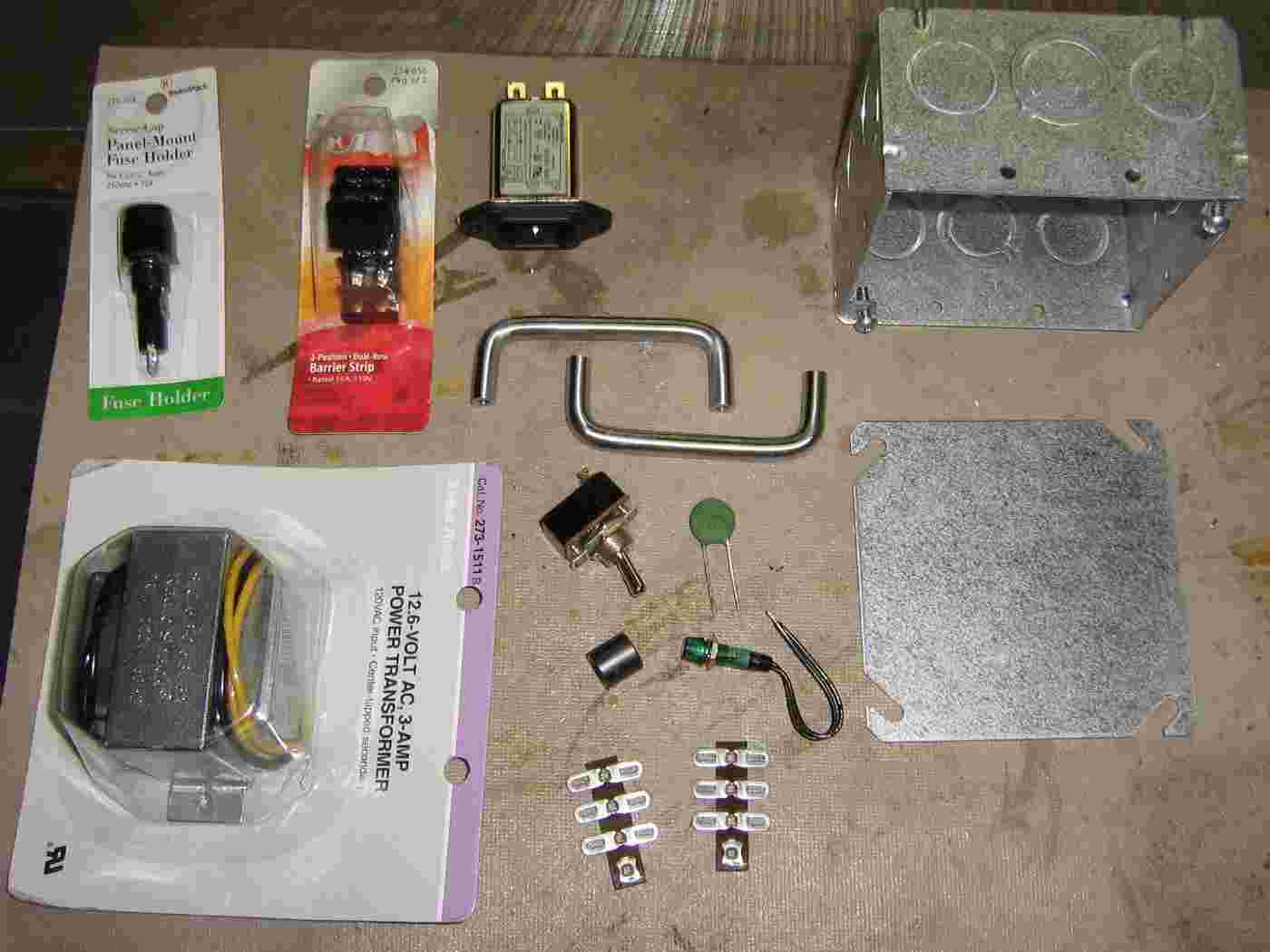
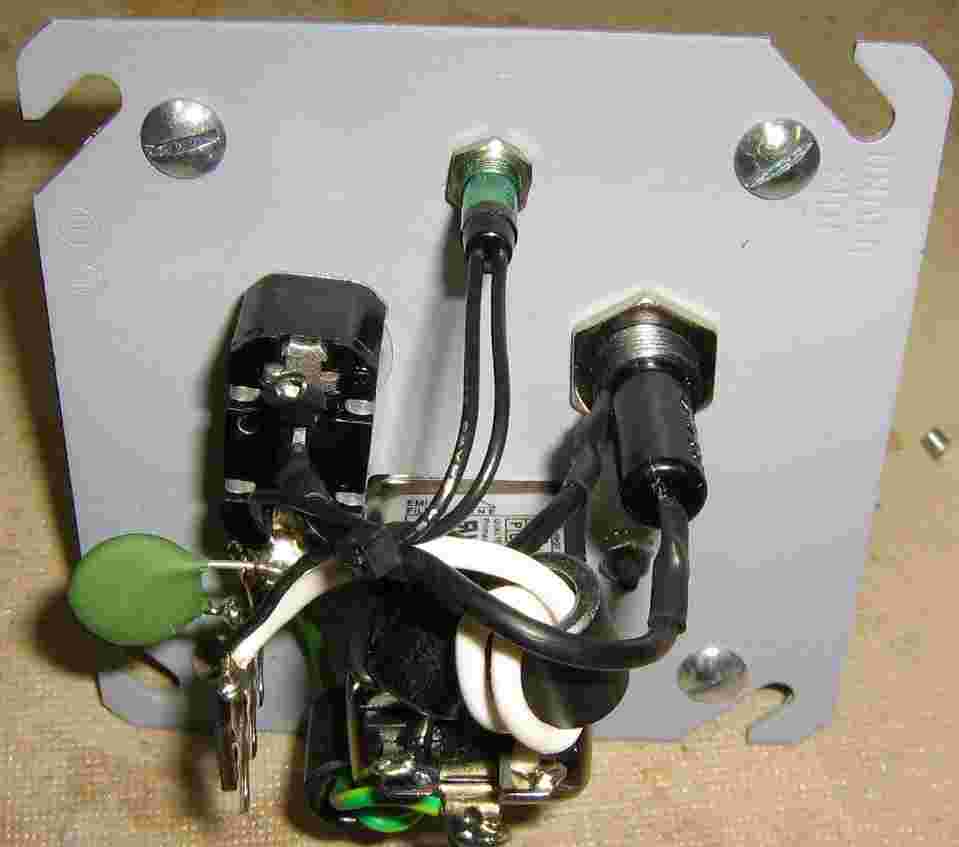
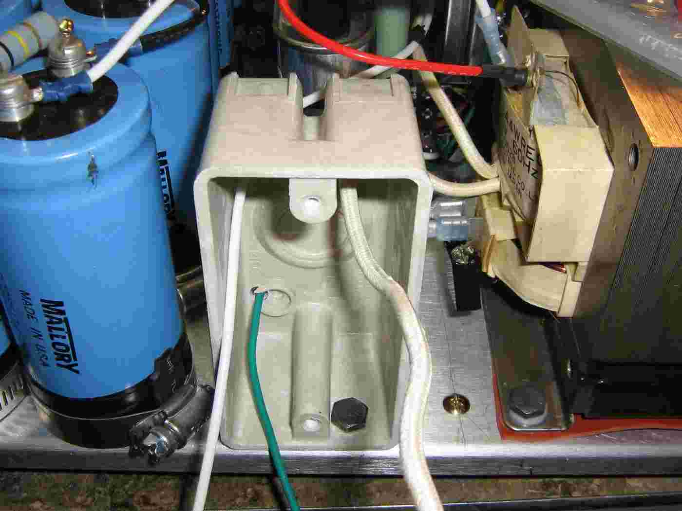
Parts for the 120 VAC main input.
A high-amperage line filter, toggle switch, and fuse holder will be mounted inside a square electrical outlet box. The filtered 120 VAC lines will be mounted on standoffs and distributed to the other transformers.
The little green blob with two leads is an input surge absorber from an old computer switching power supply. It's used to reduce the large surge current when the power is initially applied.
The Radio Shack #273-1511 transformer will provide the 12.6 VAC for the two 6MJ6 tubes (filaments in series) we will be using. It will also provide the +/- power supply for the op-amp in the control circuit.
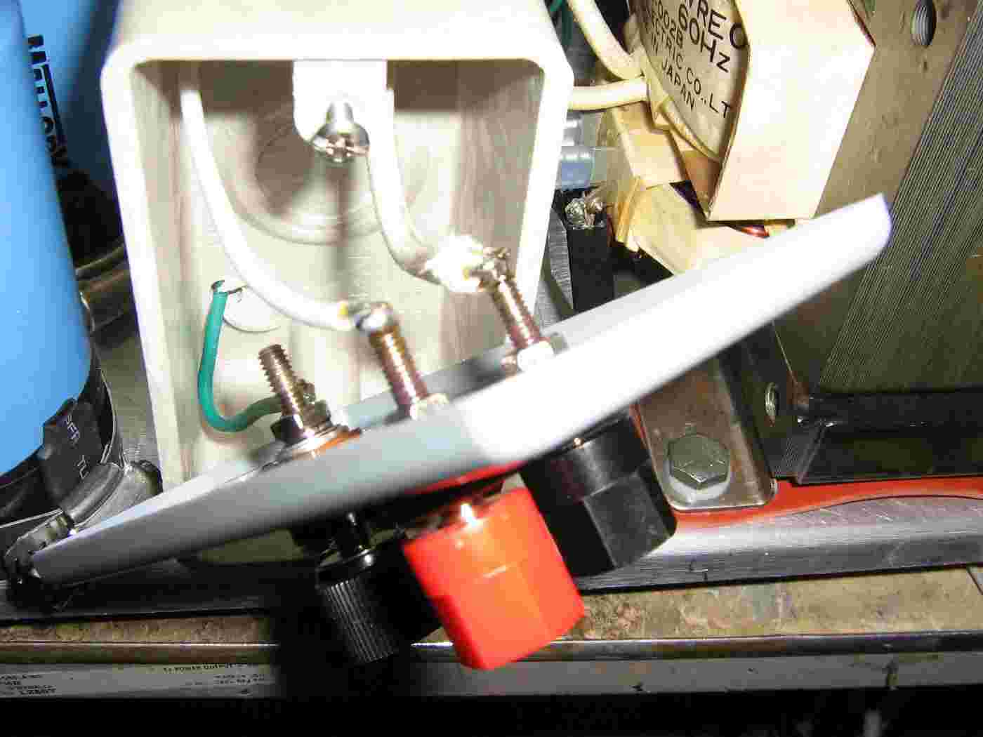
Rear view of the AC input power panel.
Try to use a single point ground to reduce any ground loops.
There are (optional) ferrite beads on the incoming 120 VAC hot, neutral, and ground leads.
A green neon lamp is used as a power indicator.
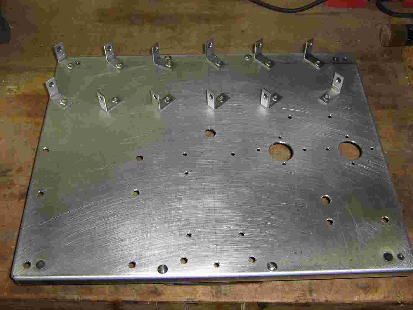
Everything will be mounted to a large aluminium plate.
L-brackets are riveted to the plate, which will be used to mount the twelve electrolytic capacitors making up the high-voltage power supply's ripple capacitor.
Secured electrolytic capacitor.
Twelve 650 µF / 450 VDC electrolytic capacitors will be used.
Put a piece of heatshrink tubing over the L-bracket and wrap the bottom of each capacitor with electrical tape.
Secure the capacitors using hose clamps.
The twelve capacitors ready to go.
Proper high-voltage construction techniques would require a little more space between the capacitors and maybe also mount them on some type of insulator. Oh well...
Wire the capacitors in series (+ to -) with a 100 kohm / 5W resistor across each one for voltage load sharing.
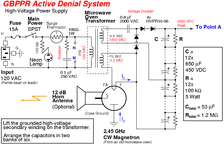
Stock microwave oven transformer.
Its secondary provides 3.3 VAC for the magnetron's filament and the high-voltage winding provides around 1,800 VAC.
Note that one side of the high-voltage winding is connected to the frame of the transformer (ground). This will need to be disconnected and properly isolated.
The magnetic shunts, which are normally installed in a microwave oven transformer, can stay.
On the two bottom spade connectors for the 120 VAC primary input, a resistor/capacitor snubber circuit is used to clamp any high-voltage spikes or kick-backs.
Isolating the high-voltage secondary.
The grounded end was unsoldered and connected to a little stand-off terminal mounted on the transformer's protective cardboard.
Not all transformers will be the same, but they will all have one side of the high-voltage winding tied to ground, either with a screw or a solder tab.
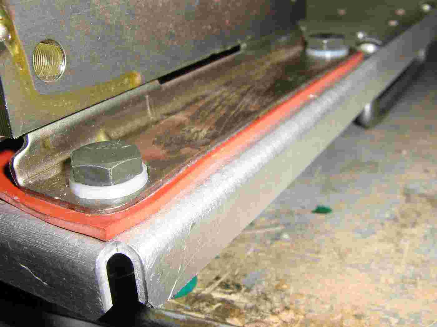
The case of the transformer was further isolated from the chassis ground using a rubber gasket sheet and nylon washers on the mounting bolts.
This is to help reduce any 60 Hz hum, if you'd ever wish to modulate the magnetron's output in the future, so it's not really a requirement.
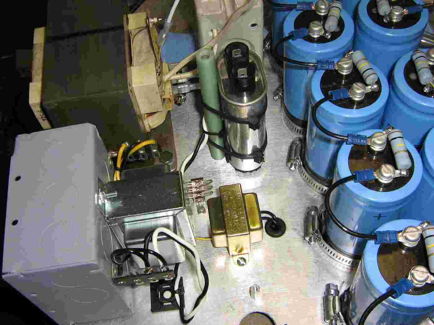
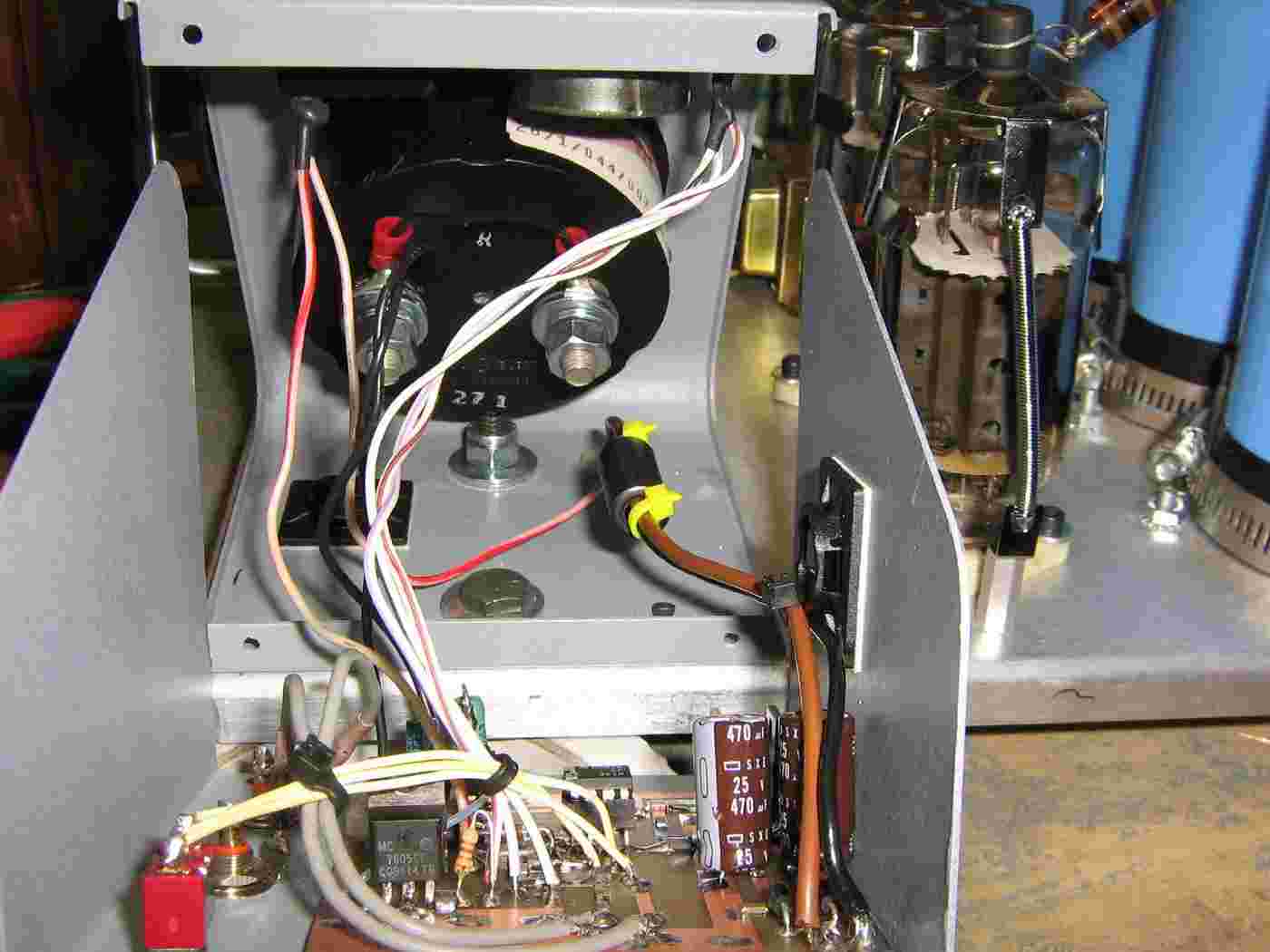
Overview of the 6MJ6's filament transformer (silver-colored - mounted on the electrical box) and also the grid voltage transformer (gold-colored).
The series 0.8 µF capacitor in the voltage-doubling circuit is isolated from ground by Zip-tying it to a plastic rod.
You can also see the high-voltage load sharing resistors (100 kohm / 5W) aross each of the electrolytic capacitors. These will also help to dissipate any stray voltage when the power is off.
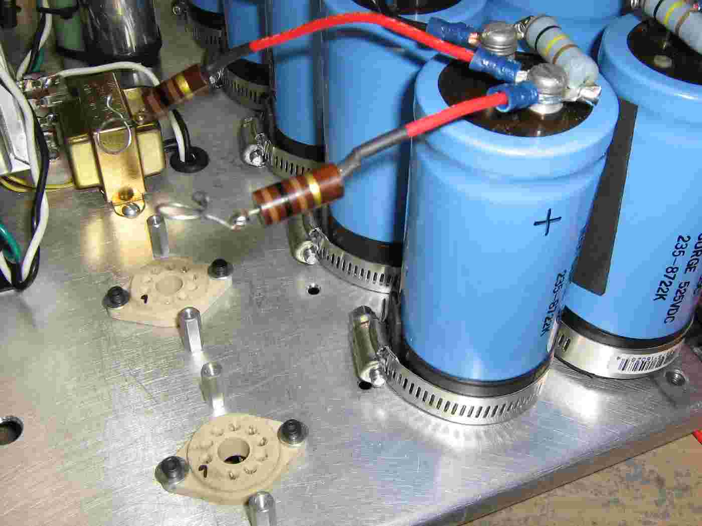
High-voltage output from the capacitor bank.
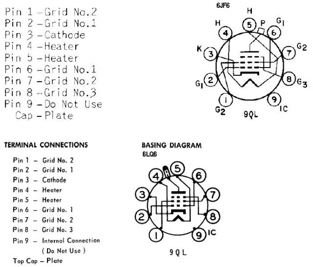
Little spring clips were made to connect the 100 ohm resistors to the top cap (plate) on the two 6MJ6s.
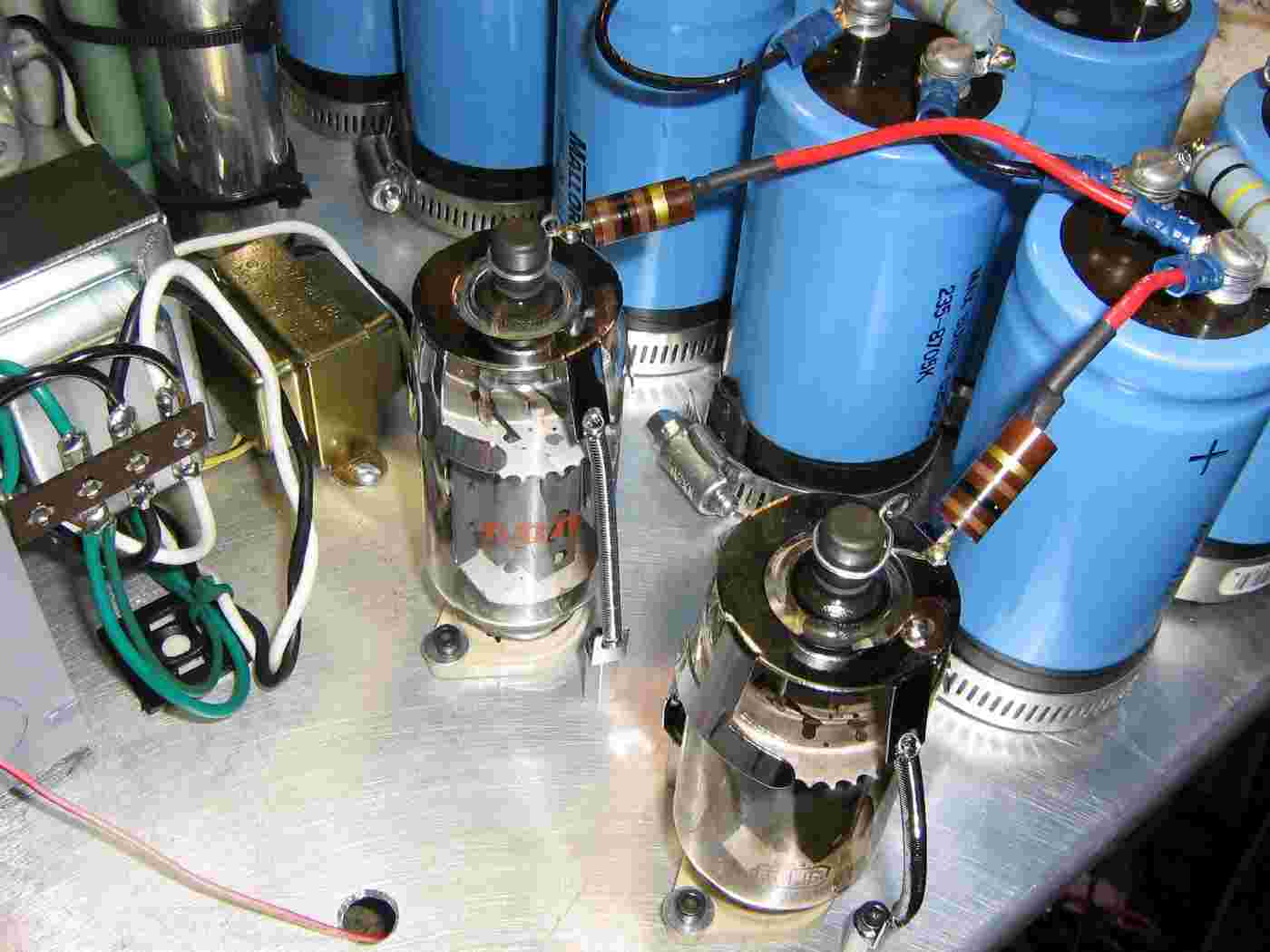
6MJ6s in place.
Optional spring retainers hold the tubes in place.
The tube on the lower-right is the "A" tube, the other is the "B" tube.
Underside view of the mounting plate showing the tube socket wiring and grid voltage circuit.
The top socket is for the "A" tube, the other is for the "B" tube.
The 6MJ6's have their filaments wired in series so they can be driven directly with the 12.6 VAC secondary from a Radio Shack #273-1511 transformer.
Note the nylon insulation washers on the microwave oven transformer's mounting bolts (lower-left).
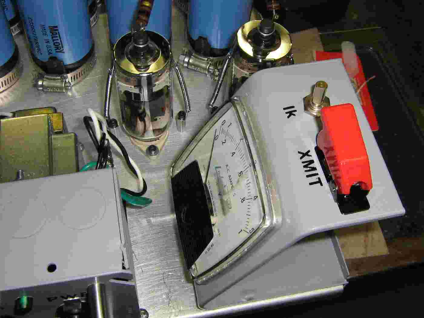
Magnetron current meter, magnetron cathode current control (Ik), and the transmit-enable (XMIT) switch.
The meter is from an old Lab-Volt trainer used in schools. Its full-scale reading is 500 mA DC.
HVPR16-06 high-voltage diodes in the voltage doubler circuit.
Leaving the shunts in the microwave oven transformer also helps to suppress the large surge current when first powered on. This is necessary to protect the diodes from any over-current transients.
Use two diodes in series, as shown, just to be safe.
HVPR16-06 Diode Specifications VR 6,000 Volts IF 550 mA VF10.00 Volts
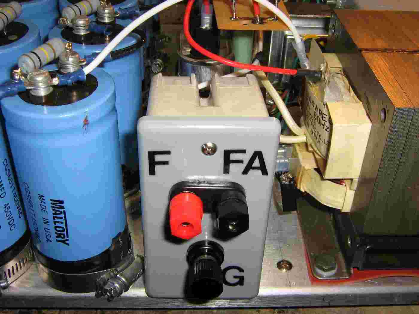
The final high-voltage output connectors will be mounted in a fiberglass electrical box. The magnetron connections will be via banana jacks.
Connect the banana jacks like so. Note that the direct filament winding on the microwave oven transformer usually goes to the magnetron's "FA" terminal. Every schematic or datasheet shows them connected differently, so I don't know on that one...
Also note the isolated ground lug. This ties back to the single point ground in the main incoming voltage electrical box.
Completed high-voltage magnetron connection plate.
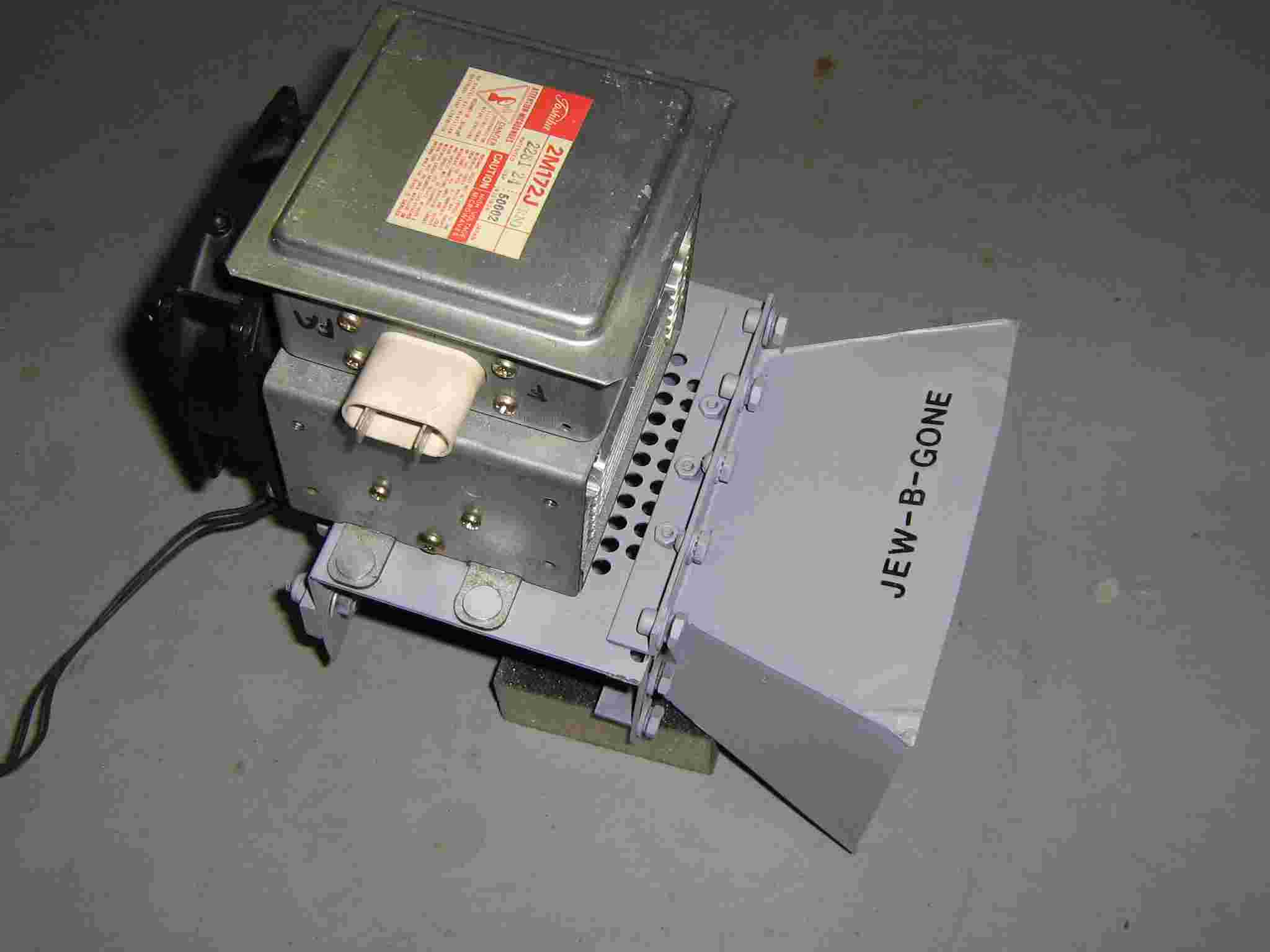
Toshiba 2M172J magnetron mounted to the horn assembly built in GBPPR 'Zine, Issue #55.
The horn has a mounting bracket in the rear to allow for mounting at the focal point of a parabolic dish.
A large 120 VAC fan provides continuous air flow over the magnetron's cooling fins.
Raytheon markets their Active Denial System for "riot control."
This one is designed for "Bolshevik control."
"'Nobody wants to be on the wrong side of Ari Emanuel, especially now that his brother is running the White House,' said one television executive, who asked for anonymity to preserve harmony with him."
--- June 9, 2009 quote about Ariel Emanuel, Jewish supremacist Rahm Emanuel's brother, in the New York Times (of all places).
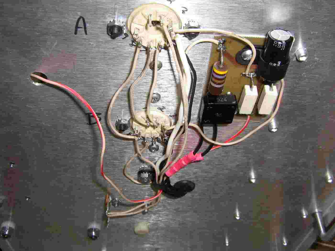
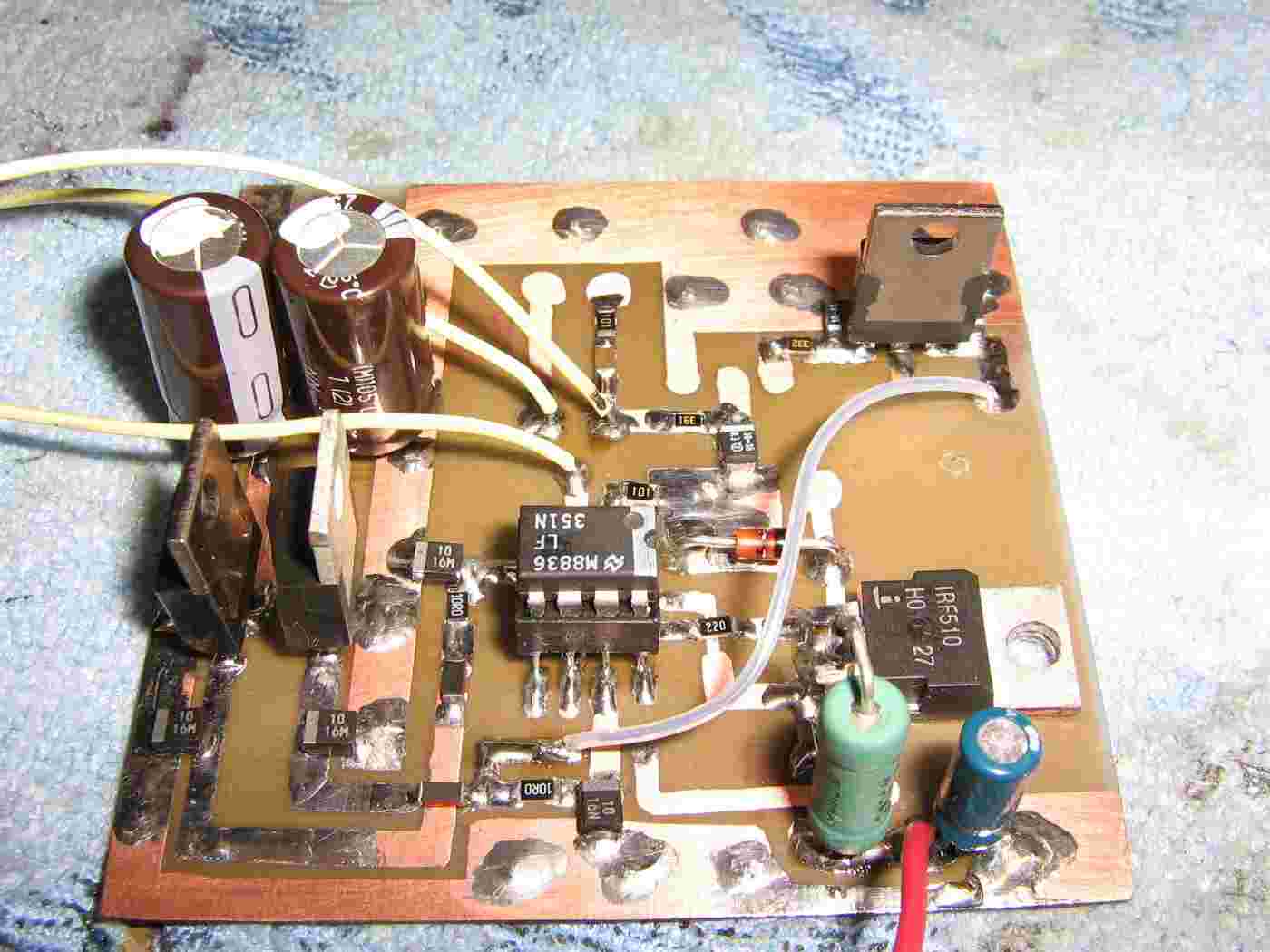
Current sink circuit board.
Differs slightly from the original 73 article due to not having all the same parts. Should work fine though, except for amateur television transmissions.
A LF351 op-amp replaces the circuit's original LF357. The LF351's voltage is regulated via (optional) 7812 and 7912 regulators. An IRF510 N-channel MOSFET replaces the VN66AF.
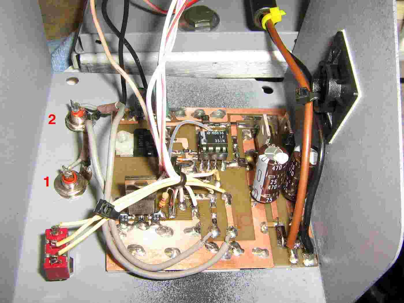
Mounting the control circuit board.
The two phono jack inputs are for external current control and modulation input. These will be for upcoming projects.
The Input Select switch is on the lower-left. The Modulation Input #1 is the phono jack below that, then the Modulation Input #2 (direct) phono jack.
Final wiring showing the current meter, transmit switch, and 1 kohm current control potentiometer.
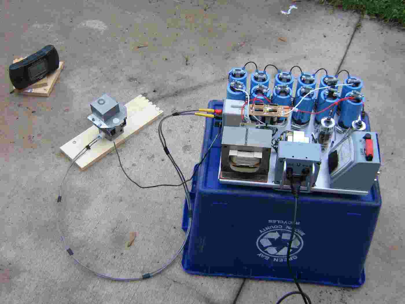
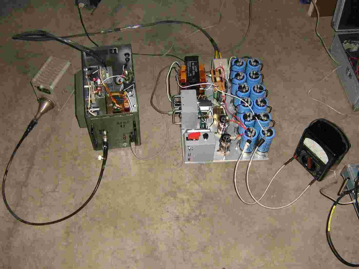
Outside test setup.
Wasn't sure if it would work or not, but remarkably, everything did check out.
An Atari Lynx is used as a RF output indicator.
The high-voltage lines to the magnetron are run through vinyl tubing for extra insulation.
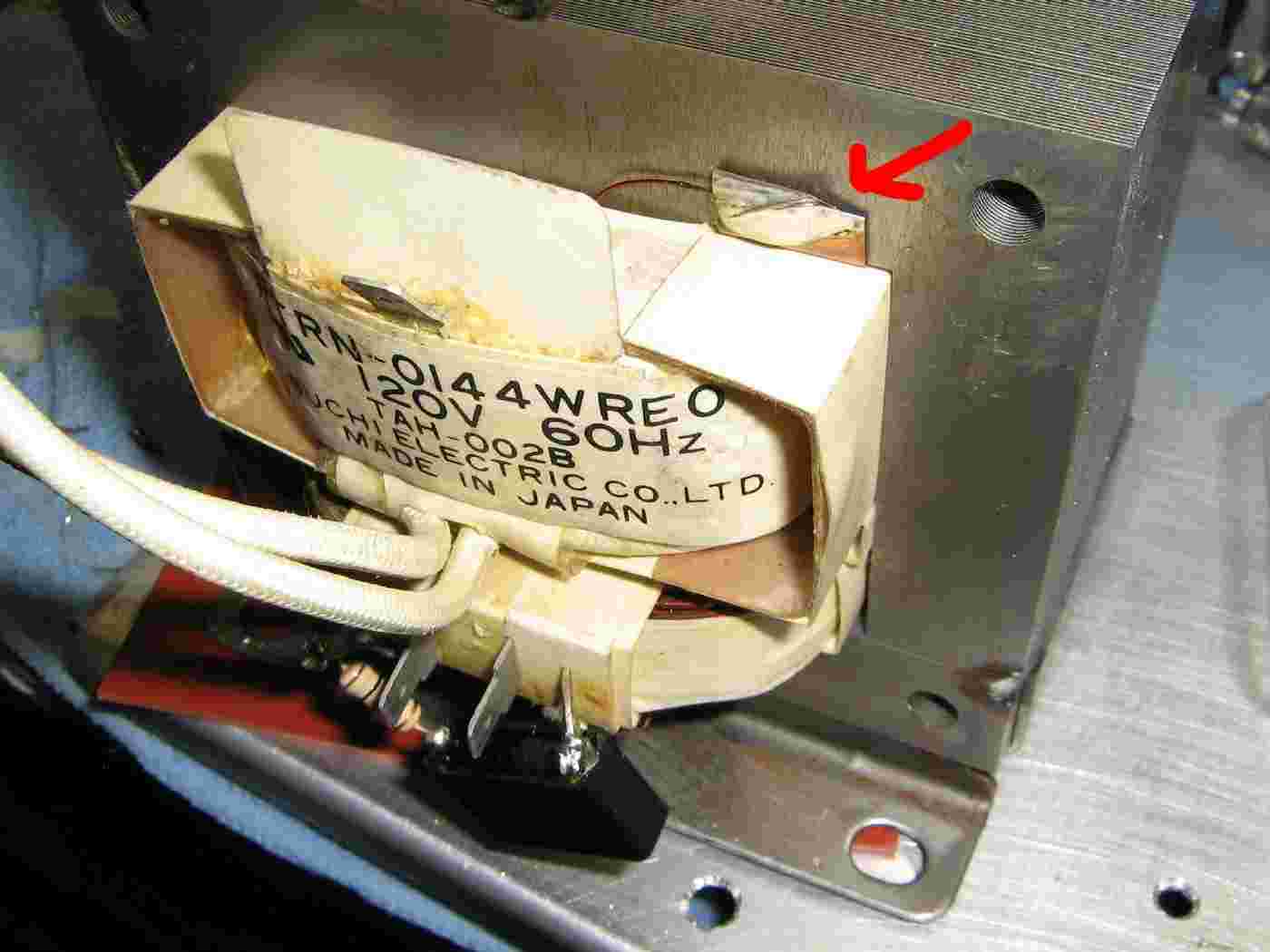
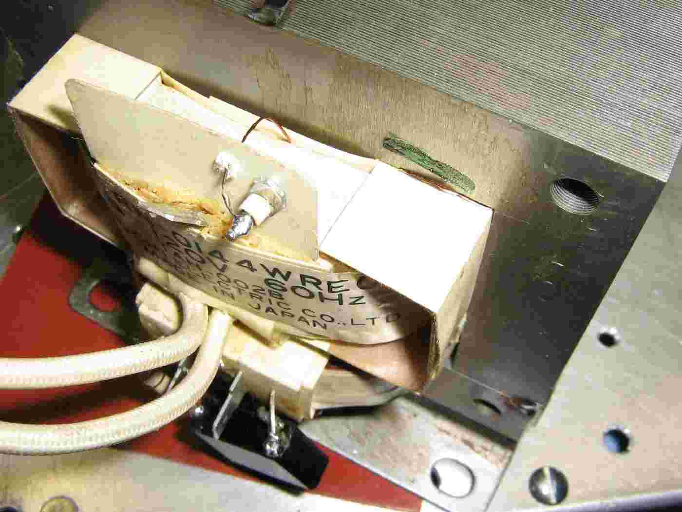
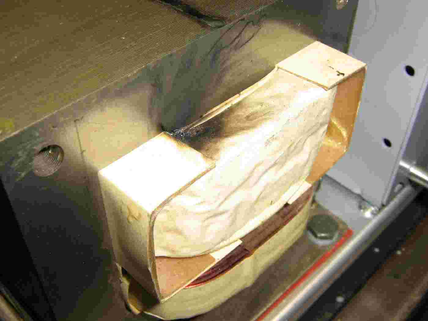
Then it blew up...
Microwave oven transformers are not really designed for continuous current operations, or for use in "real" high-voltage power supplies.
As you can see here, the high-voltage secondary winding arced over. Try to find a microwave oven transformer that is physically large or has been coated with some type of resin or sealant.
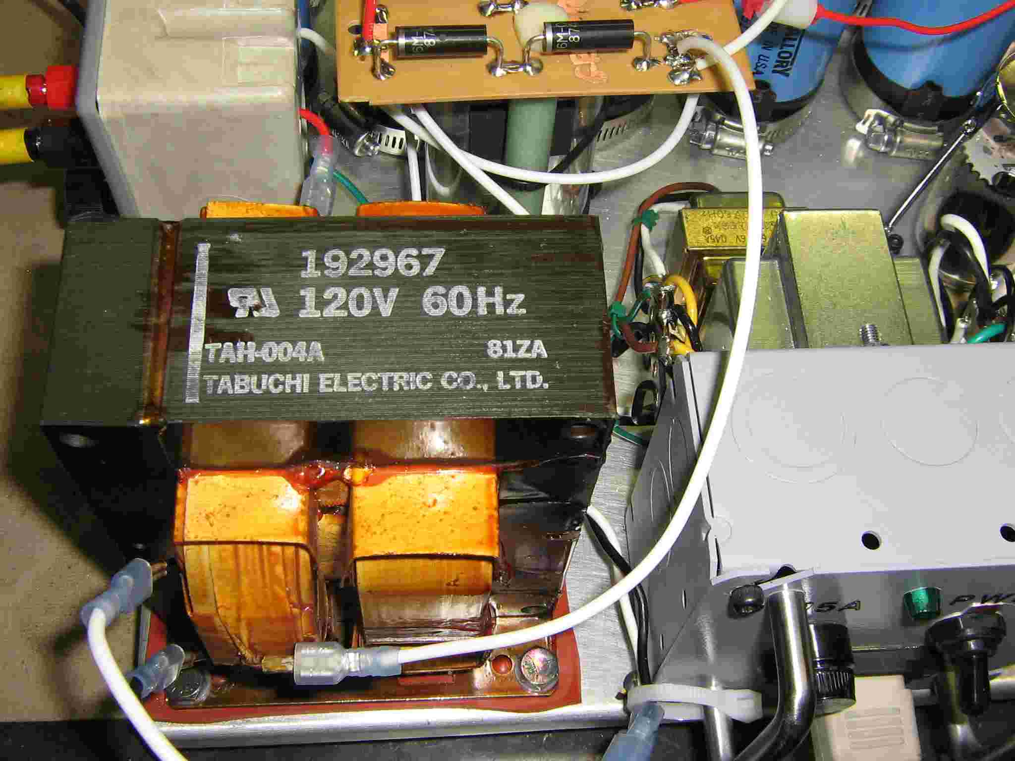
Back up and running with a new microwave oven transformer.
This transformer has been coated with some sort of "goo" to help prevent high-voltage arcing.
All microwave oven transformers are basically the same, so swapping them out should be no problem. They all seem to have slightly different mounting or wiring configurations, though.
A good secondary high-voltage winding on a microwave oven transformer will usually have a DC resistance between 50 and 120 ohms or so. The filament winding will have very low DC resistance, often below 1 ohm. You can use this to check the windings before hand.
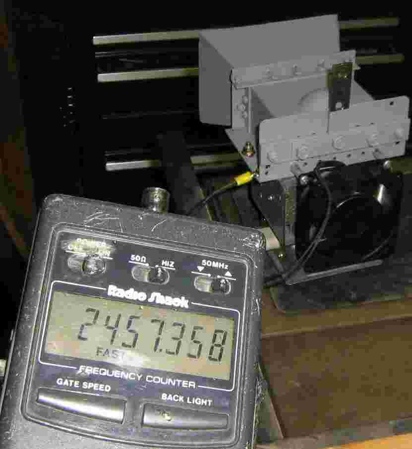
Is it bad when you can get a frequency counter reading, with no antenna, and standing behind the horn?
Test setup of the Litton 2M167 magnetron used in the 2.45 GHz Magnetron to Coax Assembly article in GBPPR 'Zine, Issue #46.
This magnetron is being run into a 50 ohm load for testing with a spectrum analyzer.
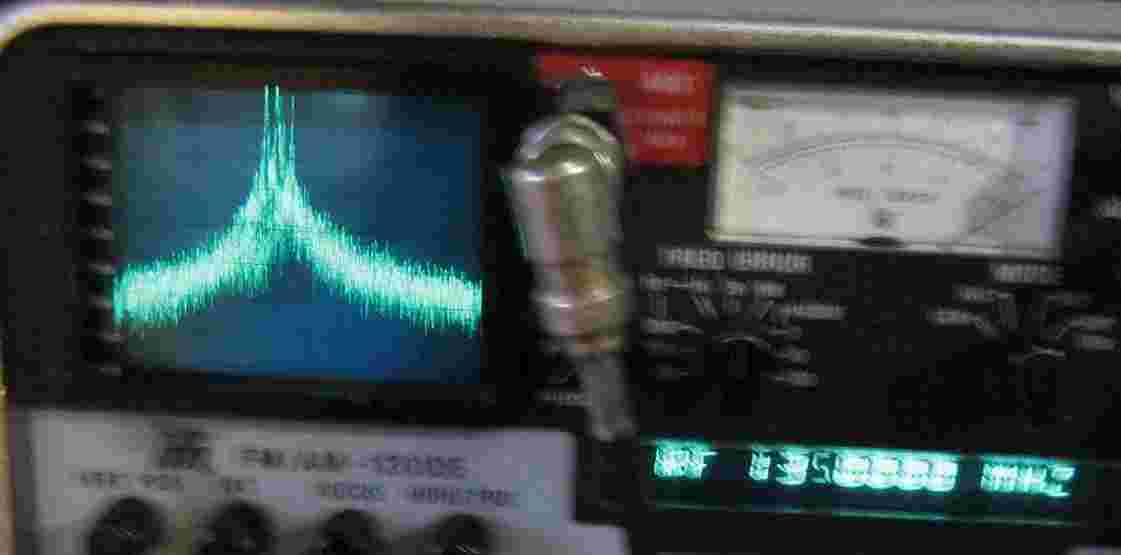
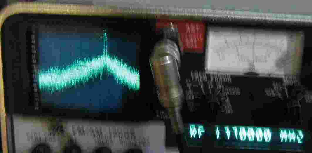
Spectrum analyzer view of the magnetron's RF output transverted (2.278 GHz LO) to fit the range of an IFR service monitor. The spectrum display is 1 MHz per division.
On the left, is the output of a Litton 2M167 magnetron. The meter is reading a center frequency of "135.0 MHz," but this converts to an actual output frequency of 2.413 GHz. Note the output is about 1 MHz lower than the center reading. This magnetron was run into a 50 ohm load via a homebrew waveguide-to-coaxial adapter.
On the right, is the output of a Toshiba 2M172 magnetron. The meter is reading "177.0 MHz," and the signal is about 1.5 MHz higher than the center frequency. The final output frequency is around 2.4565 GHz. This magnetron was run into an open horn, so there was alot of background RF noise, which raises the noise floor on the analyzer.
Schematics
- It gets hot! Very hot! Both the 6MJ6 tubes and the magnetron. Forced air cooling is a must!
- The filaments in the 6MJ6 tubes and the magnetron need to be warmed up prior to applying the plate voltage (i.e., flipping the "XMIT" switch). Give it a good 30 seconds or so.
- The (stock) current control circuit appears to top out around 200 mA into the magnetron. Some magnetrons will require higher current for a cleaner RF output spectrum. Experiment with different magnetrons, if you can.
- Turn the magnetron's cathode current control (Ik) down before you activate the XMIT switch. The magnetron seems to perform better with a slowly increasing cathode current.
- Mount the magnetron/horn assembly at the focal point of a 24 dB WiFi parabolic dish for an ERP output of around 100 kW or more!
- The magnetron's RF output signal tends to "jump" around a bit in frequency, especially if the current is too low.
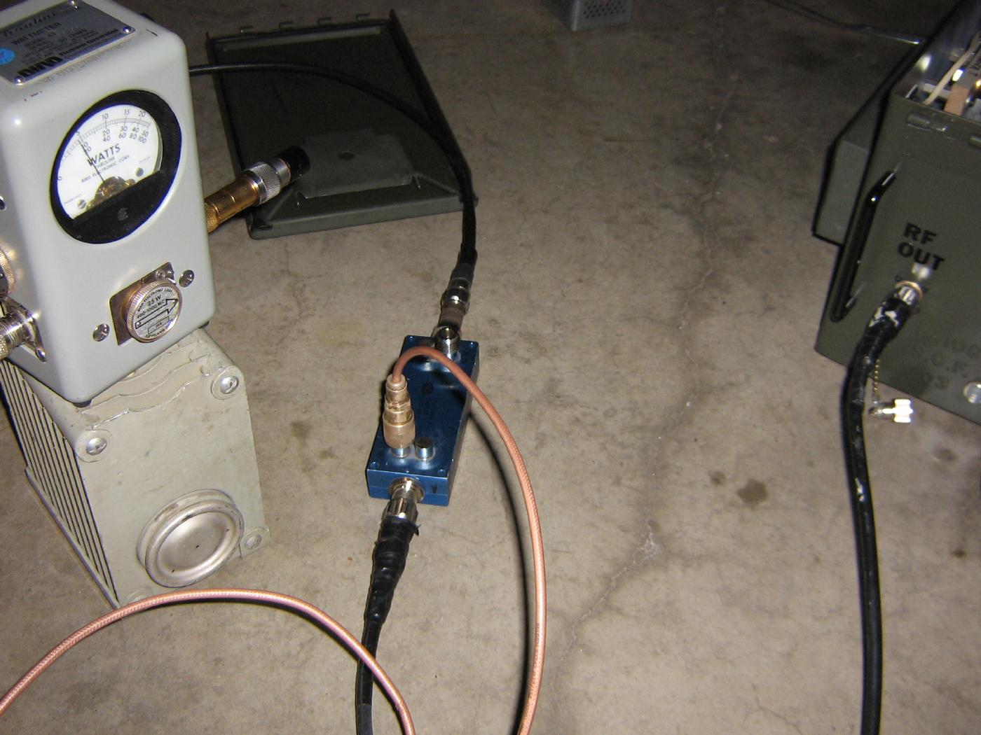
- 2M167 Magnetron RF Output Power Test A Bird 43 wattmeter with a "25 W / 400-1000 MHz" slug is reading around 5 watts (+37 dBm) and the magnetron is connected via a 20 dB directional coupler. RF output power is then (potentially) around 500 watts (+57 dBm). Not sure how much error is from the out-of-band Bird slug, though.
Microwave Oven Magnetron Current Recommendations Oven Manufacturer Operating Current (mA) Litton 160 - 300 Sharp 200 - 450 Tappan 250 - 325 Whirlpool 240 - 300 Sanyo 200 - 270 Amana RC-10 400 - 500 (1,000 Watts) Litton 70-40 600 - 650 (1,000 Watts) Litton 80-50 600 - - (1,300 Watts) Litton 550 500 - 600 (1,300 Watts) Sharp R-22 350 - 450 (1,000 Watts) Compiled from various repair notes.
Notes & Datasheets


SecretKeyFactory skf = SecretKeyFactory.getInstance("DESede");SecretKeyFactory skf = SecretKeyFactory.getInstance("AES");SecretKeyFactory skf = SecretKeyFactory.getInstance("DES"); OK, because you took the time to create an MCVE:
http://stackoverflow.com/questions/26828649/diffiehellman-key-exchange-to-aes-or-desede-in-java

|
|
How can I decrypt TLS messages when an ephemeral Diffie-Hellman
ciphersuite is used? I am able to expose the premaster secret and master
secret from the SSL Client. Using that, how to decrypt the messages in
Wireshark?
http://security.stackexchange.com/questions/35639/decrypting-tls-in-wireshark-when-using-dhe-rsa-ciphersuites LARGE PRE-MASTER SECRET GENERATED FROM 2048 BIT DH KEY NOT DIGES TED IN TLSV1 AND TLSV1.1This problem happens because the large pre-master secret
generated from 2048 bit DH key was not properly hashed to derive
the master secret.
http://www-01.ibm.com/support/docview.wss?uid=swg1IV74069
How are TLSv1.0 ciphers negotiated as TLSv1.2?
Ok what about 1.2 suites such as TLS_RSA
WITH_AES_256_CBC_SHA256 or TLS_ECDHE_RSA_WITH_AES_256_CBC_SHA384? Can a
client/server negotiate these if they only support TLSv1.0?
Technically a client and server can negotiate
whatever they're configured to negotiate and support. The cipher suite
format hasn't changed between TLSv1 and TLSv1.2. Just the meaning of
the elements. If the client and server both support TLS_RSA
WITH_AES_256_CBC_SHA256 then it will be used. If TLSv1.0 is used it
will still work. If TLSv1.2 is used it will still work. The only
different is in how the negotiated hashing algorithm is used.
Enable TLS 1.1 and 1.2 for Clients on Java 7How do I administratively enable TLS 1.1 and 1.2 system wide? http://superuser.com/questions/747377/enable-tls-1-1-and-1-2-for-clients-on-java-7 .. |
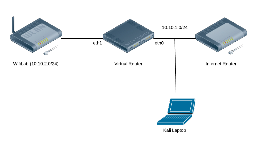
pam_exec. By using the pam_exec module, we can have an arbitrary command run on log in/out, which can setup and reset the IPTables REDIRECT via an SSH tunnel to my Burp Proxy./etc/pam.d/common-session:session optional pam_exec.so log=/var/log/burp.log /opt/burp.sh
#!/bin/bash

BURP_PORT=8080
BURP_USER=tap
LAN_IF=eth1

set -o nounset

function ipt_command {
 ACTION=$1
 echo iptables -t nat $ACTION PREROUTING -i $LAN_IF -p tcp -m multiport --dports 80,443 -j REDIRECT --to-ports $BURP_PORT\;
 echo iptables $ACTION INPUT -i $LAN_IF -p tcp --dport $BURP_PORT -j ACCEPT\;
}

if [ $PAM_USER != $BURP_USER ] ; then
 exit 0
fi

if [ $PAM_TTY != "ssh" ] ; then
 exit 0
fi

if [ $PAM_TYPE == "open_session" ] ; then
 CMD=`ipt_command -I`
elif [ $PAM_TYPE == "close_session" ] ; then
 CMD=`ipt_command -D`
fi

date
echo $CMD

eval $CMD
$LAN_IF
destined for ports 80 and 443 to local port 8080. This does have the
downside of missing traffic on other ports, but this will get nearly all
HTTP(S) traffic.REDIRECT
target still maintains the same interface as the original incoming
connection, we need to allow our SSH Port Forward to bind to all
interfaces. Add this line to /etc/ssh/sshd_config and restart SSH:GatewayPorts clientspecified
/etc/java-6-openjdk/security/java.security, comment out the line with security.provider.9=sun.security.pkcs11.SunPKCS11 ${java.home}/lib/security/nss.cfg.wifilab server is pretty straightforward. You can either use the -R command-line option, or better, set things up in ~/.ssh/config.Host wifitap
User tap
Hostname wifilab
RemoteForward *:8080 localhost:8081
tap on host wifilab, forwarding local port 8081 to port 8080 on the wifilab machine. The * for a hostname is to ensure it binds to all interfaces (0.0.0.0), not just localhost.burp.der./system/etc/security/cacerts, and expects OpenSSL-hashed naming, like a0b1c2d3.0
for the certificate names. Another complication is that it’s looking
for PEM-formatted certificates, and the export from Burp is
DER-formatted. We’ll fix all that up in one chain of OpenSSL commands:(openssl x509 -inform DER -outform PEM -in burp.der;
openssl x509 -inform DER -in burp.der -text -fingerprint -noout
) > /tmp/`openssl x509 -inform DER -in burp.der -subject_hash -noout`.0
-subject_hash_old
if you’re using an older version of Android. Installing is a pretty
simple task (replace HASH.0 with the filename produced by the command
above):$ adb push HASH.0 /tmp/HASH.0
$ adb shell
android$ su
android# mount -o remount,rw /system
android# cp /tmp/HASH.0 /system/etc/security/cacerts/
android# chmod 644 /system/etc/security/cacerts/HASH.0
android# reboot
ssh wifitap
from your Kali install running Burp, and you should see your HTTP(S)
traffic in Burp (excepting apps that use pinned certificates, that’s
another matter entirely). You can check your installed certificate from
the Android Security Settings.| See the latest release on Github for source, OSX and Windows builds. |
http://www.techno-holics.com

So.... I finally got hold of a couple of the Parallax serial RFID readers from Radioshack. I had the Northwest depot send a couple to my local store. $9 each is quite a steal. I set to work repurposing my Arduino to interpret the signal and output the RS232 into the virtual com port that the Arduino driver installs.

I'm running Windows 7 and there used to be a super awesome option called serial keys in Windows XP. This option no longer exists. I had to find a way to get the input from the com port to dump into the keyboard buffer. After some searching, I located a program called AAC Keys, which is an alternative to the Windows serial keys application. It's lightweight, runs in the tray, and can be configured to any com port you wish.

My original goal was to do a sort of Windows login authentication using my RFID implant's unique tag.... But i'm not going to get into what a headache that was to try to do using an Arduino to interpret the signal. So I have put that project aside and decided to have some fun logging into various sites and applications using my tag as the password. For demonstrative purposes, I changed my Guild Wars password as well as the password to the RFIDtoys forums to match that of my tag. Since the sketch I uploaded for my Arduino automatically sends a 'return' at the end of the tag, it was a simple matter of scanning my tag when my cursor was in an active text box.

This is a video of it in action.

The programs I used for this were:

Arduino FTDI drivers:

http://www.ftdichip.com/Drivers/VCP.htm

AAC Keys:

http://www.aacinstitute.org/downloads/aackeys/AACKeys.html

Notable mentions:

Guild Wars

Google Chrome

All in all, it's a fairly simple little project. I am quite happy with how it turned out. And it gave me a nice little break from fighting with Windows to get my station login system working.
http://usabuzz.net/page/watch/vid2016W6FRRaWo60w
https://cnnportugal.iol.pt/siresp/relatorio-siresp/versao-publica-do-relatorio-do-siresp-foi-cortada-e-ocultou-falhas-da-nos/20260602/6a1f...


