The Unwanted Blog
Rockets, cats, aircraft, guns, politics, photography, science fiction. You know, the usual stuff.
Search Results : nuclear light bulb » The Unwanted Blog
Jul122012
Cyanotype Print 01: Nuclear Light Bulb
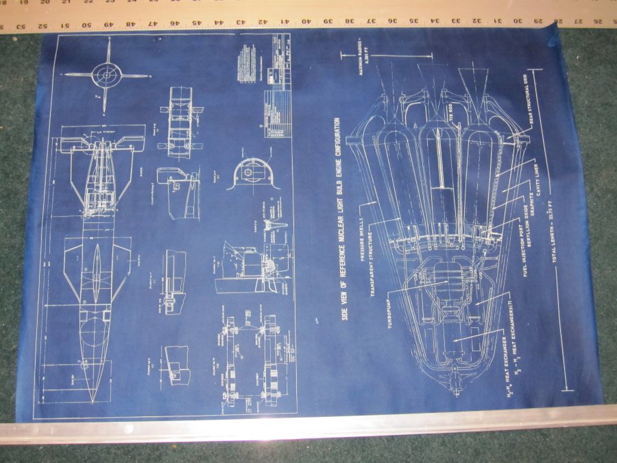
A NASA diagram of a Nuclear Light Bulb, an advanced nuclear rocket that uses incandescent uranium plasma to irradiate hydrogen gas to provide thrust. NOTE: There is a mis-spelled word on the blueprint. It was mis-spelled by NASA way back when… it’s shown as it was published.

A hand made cyanotype blueprint on sturdy 12X18 watercolor paper. Each is unique, and likely to feature small imperfections.The blue will fade if left in the sun. If this happens, it can be darkened by placing it somewhere dark with good air flow to re-oxidize the ink. Alternatively. hydrogen peroxide, available from grocery stores, will instantly oxidize the ink and restore it to its full hue.
Jul282010
To continue…
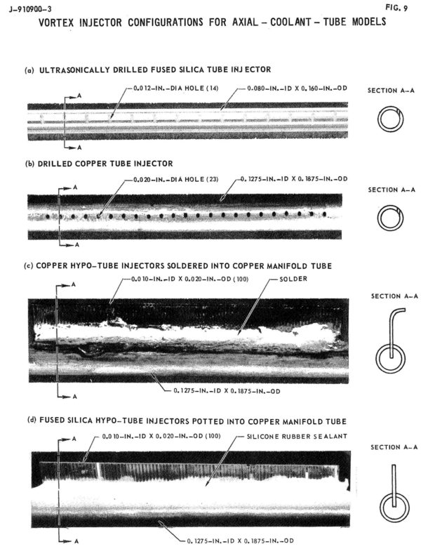
A uranium plasma with a core temperature of 42,000 degrees Rankine (23,333 K) is simply incapable of being held by any solid structure. The highest melting point of any known substance is tantalum hafnium carbide, at 4488 K. The uranium plasma would simply evaporate any material it came into contact with.So, the trick was to make sure the uranium plasma didn’t come into contact with any solid materials. To do this, a “radial inflow vortex” was to be employed. Within the cylindrical reactor chambers, the uranium plasma would be held within the center, away from direct contact with the walls, by a rapidly rotating sheath of neon gas. Injected tangentially along the walls, the neon gas would travel in a helical pattern up the length of the cylinder and would be extracted at the forward end, to be cooled and recycled back into the system. The rapid rotation of the neon gas would be translated to the uranium plasma, and the whole plug of gas would spin at a high rate. Centrifugal force would keep the system properly distributed… while normally it would seem that a uranium gas would be denser than neon, the fact was that at the fabulously high temperatures involved, the uranium would be lower density than the cooler neon, and thus would be suspended in the core, away from the walls.
While the core temperature of the uranium plasma was 42,000 R, the outer surface would be a comparatively chilly 15,000 R. This is of course still far in excess of what any material structure can handle. But the neon, already a gas, could handle 15,000 R; due to the vortext structure, the innermost surface of the neon layer, where it was in contact with the uranium, would also be at 15,000 R, but a steep temperature gradient dropped the temperature to a modest, and structurally possible, temperature of 2000 R at the walls. The thickness of the neon gas layer was estimated to be under 0.05 feet.
Each of the seven chambers would have a neon flow rate of 2.96 pounds per second, and an axial velocity of 1.95 feet per second and a tangential velocity of 10 feet per second, with a total dwell time of 3.8 seconds. The hot neon would extract energy from the reactor, of course, to the sum of 4,120 BTU/sec. The hot neon would be used, in part, to pre-warm the hydrogen fuel.
—————–
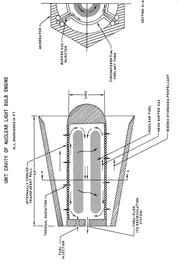
Schematic view of one of the seven chambers in the nuclear lightbulb engine (United Aircraft)
————–
Even with the neon buffer layer, a simple glass wall would not be sufficient to withstand the harsh environment. As well as simply being in contact with 2000 R neon gas, the transparent wall would also have a vast sleet of radiation passing through it… infra-red, gamma rays, neutrons, the whole spectrum. Once again there was the problem that no transparent material would possibly be able to survive the environment. Even the most optically transparent material will absorb some of the radiation passing through it… and this absorbed energy will be converted directly to heat. It would not take very long at all for the clearest substance to get incredibly hot… which, of course, was the goal with the hydrogen propellant. What was desired for the propellant was manifestly not desired for the structure.
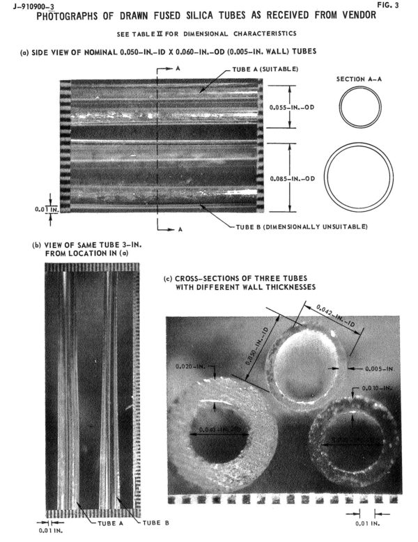
So the transparent walls were to be made not out of monolithic sheets, but thin-walled tubes. High-purity fused silica was the baselined material of choice. Thought was given to single-crystal beryllium oxide and synthetic quartz as materials, as they had better transparency in the ultraviolet, but production of the required tubes using these materials was undemonstrated. To cool the tubes, hydrogen gas would be pumped through.
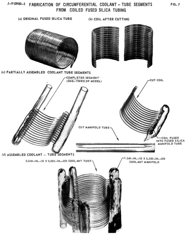
The cylindrical walls were built in three 120-degree radial segments. At the end of each segment was a manifold for injection or extraction of the hydrogen coolant, so the hydrogen did not travel very far around the circumference of the cylinder. This assured that the hydrogen did not have time to heat up to much, and that the silica glass would be maintained at a reasonably constant temperature of between 800 and 1100 Celcius (yes, the reports have units all over the place). Corning Type 7940 and General Electric Type 151 fused silicas typically had a purity of SiO2 of 99.997 percent, with Al2O3 being the primary impurity. Purity was essential… the greater the purity, the greater the transparency.
Since this was the late 1960’s, United Aircraft actually ran a number of physical experiments to demonstrate the feasibility of their designs and materials, rather than a series of colorful computer simulations. As operating a uranium plasma reaction was somewhat beyond the scope and funding of their contract with NASA, they instead used a 1.2 megawatt RF induction heater to generate an argon plasma of about 15,000 R in a subscale “reactor.” The subscale test setup used both axial tubes (with wall thicknesses down to 0.005inches) and circumferential tubes potted into the manifold with RTV silicone.
———–
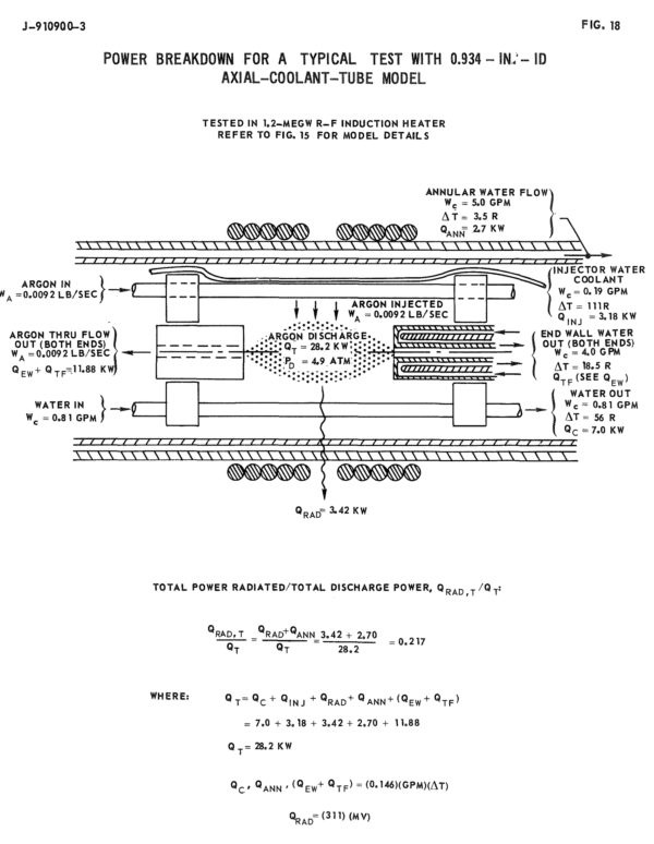
Schematic view of test setup (United Aircraft)
————–
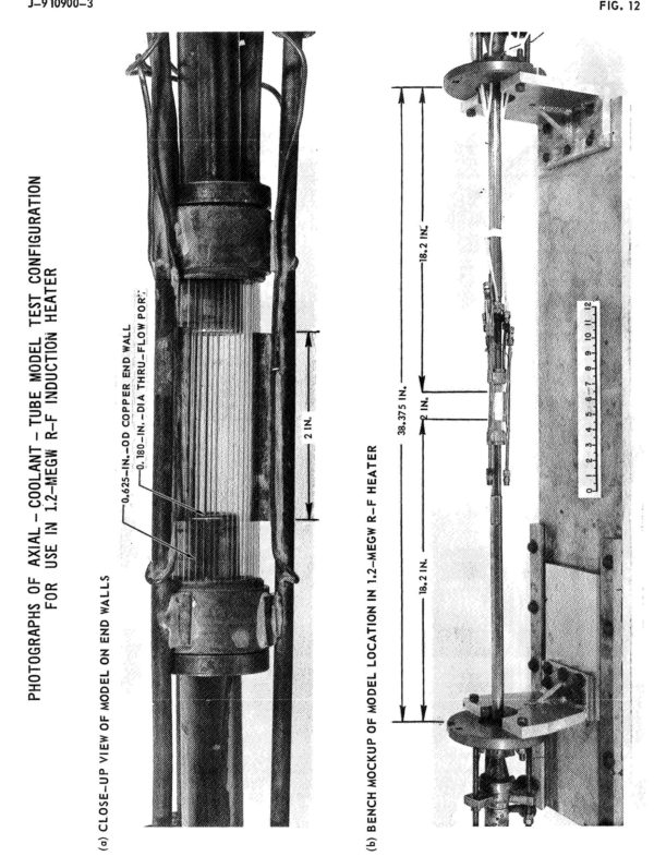
Test setup with annular tubing (United Aircraft)
————
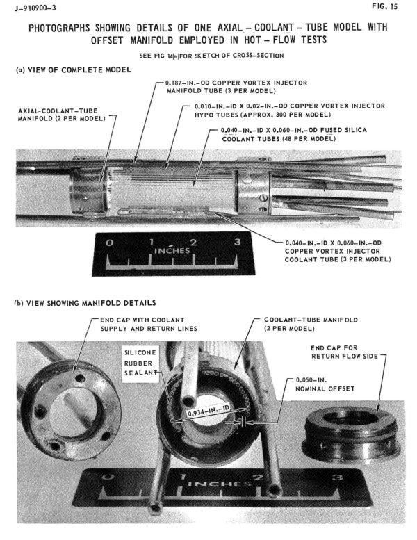
Details of test hardware (United Aircraft)
——————–
In the tests, water rather than hydrogen was used as the coolant.
Test results were generally encouraging, but a number of issues were discovered. One of the more odd things that was noted in this and other testing was that the color of the glass tubes was a variable during the course of nuclear engine operation. Radiation damage to the glass would cause the glass to gradually become blue, then purple, then black. This is, of course, fatal to not only the functioning of the engine, but the survivability of the glass. Any amount of coloring would cause massive increase in radiation absorbtion, resulting in rapid overheating and structural failure. But over 800 Celcius, the glass would thermally anneal… which would wipe out the coloration and restore transparency. Thus the need to keep the glass operating at a minimum of 800 C. But above 1100 C, devitrification of the glass would occur… it would continue to be perfectly servicable clear glass, but once it began to cool down after engine shutdown the surface of the glass would turn milky white due to a myriad of microscopic surface cracks. This would cause the glass to overheat if the engine was restarted. And thus the need to make sure that the glass did not rise above 1100 C.
————–
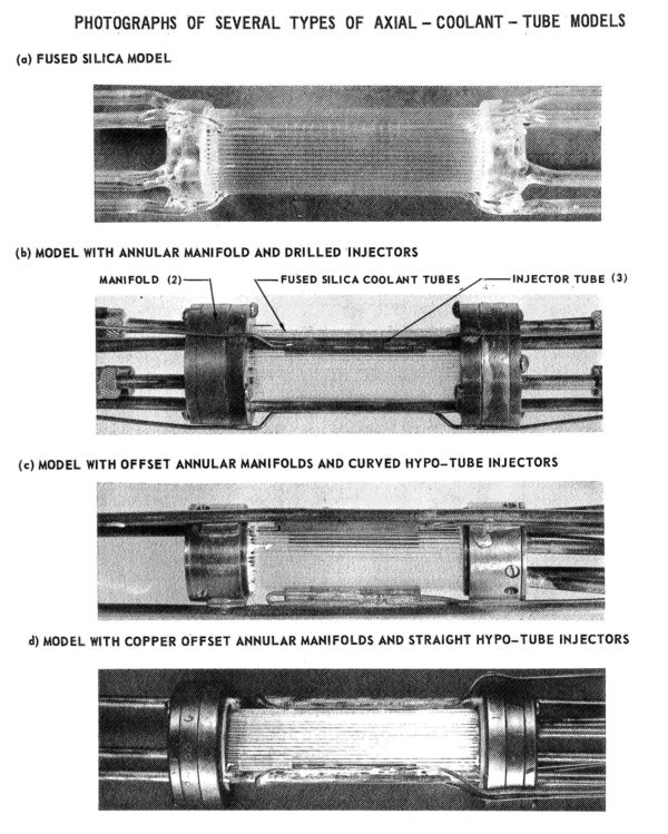

Photos of test hardware (United Aircraft)
______________
To Be Continued…
Jul172010
The operating principle of the Nuclear Lightbulb is simple: a self-sustaining uranium plasma would be contained within a glass vessel; radiant energy would pass through the “bulb” and heat hydrogen gas surrounding it, which in turn would be contained within a metal chamber. The superheated gas would then pass through a nozzle and generate thrust in the normal fashion.
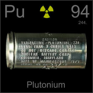
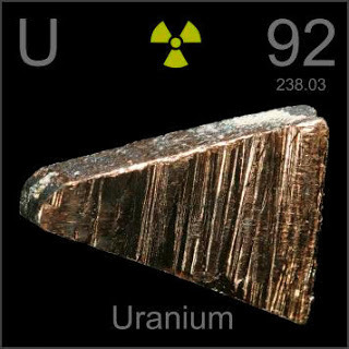
While simple to describe, almost nothin about this was simple to design. The engineering involved would have been monumental. And while the Nuclear Lightbulb is typically described in simple terms and illustrated with simple sketches, it turns out that a lot of work was done on this engine concept, (seemingly) mostly by the United Aircraft Corporation. The United Tech Research Lab produced a fairly detailed design for a reference engine, and did much more work – including many physical experiments – on the componant designs than is generally known. The reference engine had seven separate “bulbs,” each a cylinder 6 feet long by 2.3 feet in diameter. The engine operated at 500 atmospheres pressure.First off, the uranium plasma. Generating the plasma would be fairly straightforward… simply get enough of the right fissile material into an enclosed volume of the right size, and nuclear chain reactions will do the job. In this case, a critical mass of 34.7 pounds of Uranium 233 spread between the seven chambers would cause the uranium to melt, vaporize and finally become a plasma.
Step one in the process would be to actually gather that much U233 within the chambers. Obviously it could not be stored as a solid block, but instead scattered and diffuse so that nuclear reactions would not begin until it was in the reactor. In order to accomplish this, three methods were proposed:
1) Store the uranium in the form of uranium hexafluoride (UF6). The UF6 gas would be simply pumped or injected into the reactors like any other gas. Storage of the UF6 was not described, but it probably would have involved very large tanks of very low pressure (and thus low density) filled with a neutron absorbing foam. As the UF6 began to gather under increasing pressure and density, nuclear reactions would begin to take hold and the temperature would increase. At a pressure of 200 psi, the UF6 would totaly dissociate by 13,000 degrees Rankine, allowing the fluorine to be drawn off from the Uranium. The problem, of course, is that the byproduct would be fluorine gas at about 13,000 degrees Rankine. Fluorine is trouble enough at room temperature. While the gas would be cooled prior to contact with any solid structural material, fluorine that can be described in any way as “hot” is a terrifying notion.
2) Inject molten uranium. This, however, would require some means to melt the uranium, as well as inject it. The melting temperature of uranium is 1403 degrees Kelvin; while this is by no means impossibly hot to work with (metals such as tungsten and many ceramics have melting points far higher), it would still be a complication. While the plan was that the molten uranium would be injected into the reactor in the form of an aerosol suspended within a high temperature carrier gas such as neon, it was expected that the uranium would plate on the mechanical portions of the injector system.
3) A third option was similar to the molten uranium aerosol, but with the temperature lowered so that the uranium was still a solid. Here the uranium would be divided into an extremely fine dust… pumpable, injectable, would not plate out onto the structural surfaces. As the dust begins to build up within the reactor, nuclear chain reactions would cause it to heat, eventually becoming a plasma. Once the full critical mass was injected into the reactor and the system reached equilibrium, the plasma would reach an average temperature of 42,000 degrees Rankine (23,333 Kelvin). This superheated plasma would glow fiercely, providing the radiant energy needed to superheat the hydrogen propellant. But there is no material known, certainly no transparent material, that can withstand anything remotely like the temperature of the uranium plasma. A solution to containment, however, was found.
To be continued…
Jul102010
The NERVA nuclear rocket used a sorta-conventional nuclear reactor as its basis. As the reactor was brought up to power, the solid fuel elements would heat up; hydrogen would be sent through coolant channels. The hydrogen would of course heat up, cooling the reactor. When operated properly, the temperature in the reactor would reach a steady state; a temperature limited by the structural capabilities of the solid reactor materials.
The hotter the reactor, the hotter the hydrogen, and the better the rocket performance. However, the hotter it gets, the softer the reactor structural elements get; at some point it fails structurally, and perhaps even melts. So the temperature must be limited. And the temperature limits limit performance. NERVA was quite cool compared to the combustion temperature of a conventional hydrogen/oxygen rocket engine. However, the extremely low molecular weight of the pure hydrogen exhaust compared to the H2O exhaust of the chemical rocket makes up for that, providing about twice the specific impulse.In order to greatly improve specific impulse, the temperature of the hydrogen must be increased; and to do that the temperature of the reactor must be increased. It quickly becomes impossible to have a solid-core reactor, and one must accept that the uranium will not be a solid. So rocket designers of the early 1960’s came up with the liquid-core nuclear rocket, with molten uranium; and then the gas-core rocket where the uranium is so hot it has actually vaporized. But the problem was containing the uranium. Typically centrifugal force (by spinning the rocket around its central axis) was employed; the uranium liquid or gas would, hopefully, be stuck to the outer wall of the rocket reaction chamber, while lighter hydrogen would migrate to the core, and then out the nozzle. The thickness of the uranium liquid or gas would be less than the distance from the chamber wall inwards to the nozzle, so the hope was that ther uranium wouldn’t be able to flow out the nozzle. A simple idea made extremely difficult in actual practice… massive, extremely hot nuclear reactors being spun at high rate around their central axis, with little to no vibration while being injected with liquid hydrogen? Not exactly the description of a straightforward engineering problem. With all the effort involved, uranium was still expected to leak out the nozzle, making the propulsion system both filthy (a minor concern in deep space) and wasteful of uranium (a serious concern).
Another solution was devised in the mid 1960’s that in principle would combine the best of both worlds… uranium brought up to plasma temperatures, and uranium contained physically so that it could not escape. This concept was known as the Nuclear Light Bulb.
TO BE CONTINUED…
May152013
I’ve made many test runs and made considerable progress. I’ve also run out of supplies and need to improve the mechanical infrastructure. so I’ve decided to sell the “prototypes” I’ve made. These are indeed prototypes, and more to the point they are prototypes of art, so they are imperfect and variable… but they’re nevertheless pretty spiffy. These are actual cyanotype blueprints on actual vellum, an they not only look right (based on the vintage blueprints I’ve actually gotten my mitts on), they *feel* right. The failure rate is pretty high compare to the watercolor paper, but the results are much more authentic.
I currently only have a few of each. If you would like one or more of the following, send an email stating which ones to:  On a first come first served basis I’ll pass along a paypal invoice. Postage (tubes) will be $6 US, $12 everywhere else for any number.
I will update this post with revised availability numbers. When more supplies and improved infrastructure is on hand I’ll make new prints for those that requested them.
Here’s what I have (the 12X18’s were mae two at a time on 18X24 sheets an will be sliced apart):
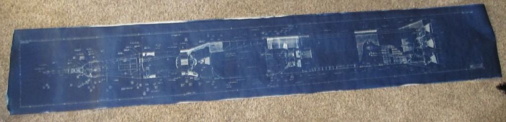
Saturn V, 1/72: messed up by being a mirror-image. D’oh. Would look good at a distance. This mirror image is $35; the final product will be $75. on hand: 1
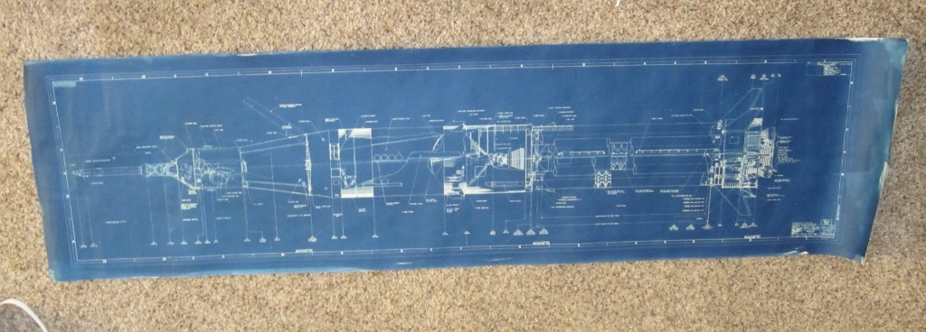
Saturn Ib, 1/72: $40 On hand: 1
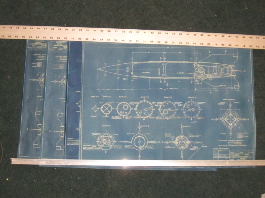
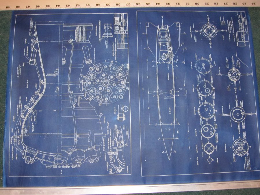
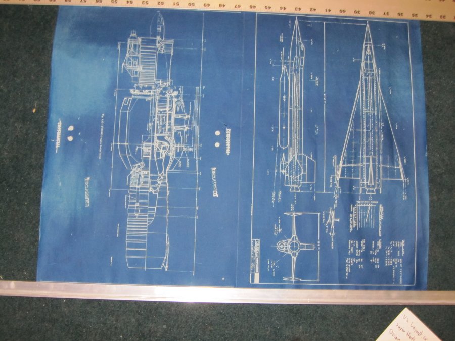
A-4 (V-2) layout drawing, 18X24 inches: $40. On hand:
A
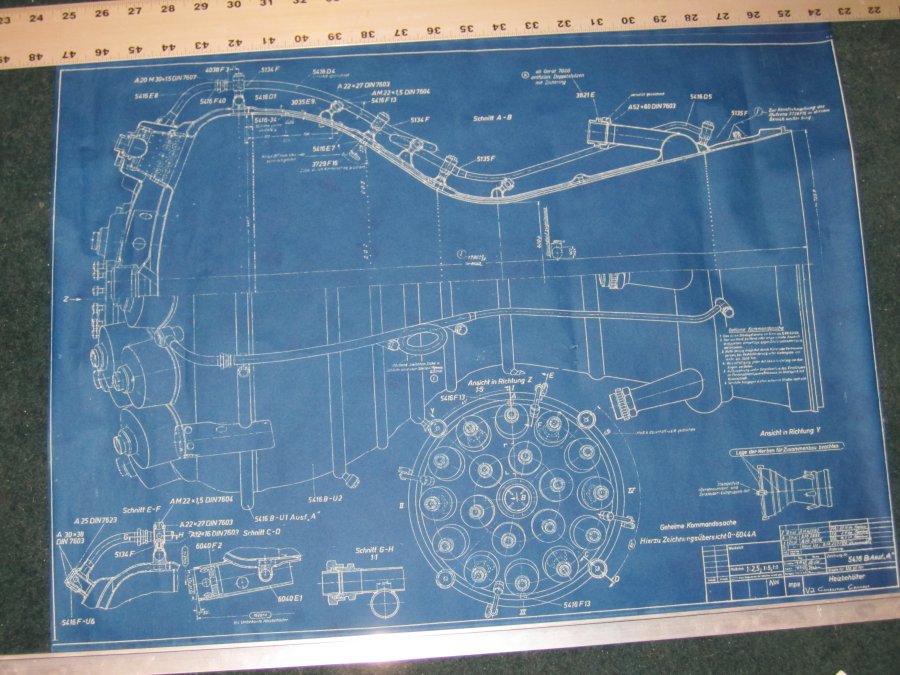
A-4 (V-2) rocket engine, 18X24 inches. $40. On hand: 1
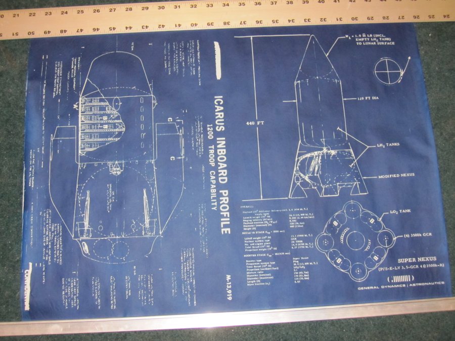
ICARUS, 12×18; $20. On hand: 1
A-4 (V-2) engine,12×18; $20. On hand: 1
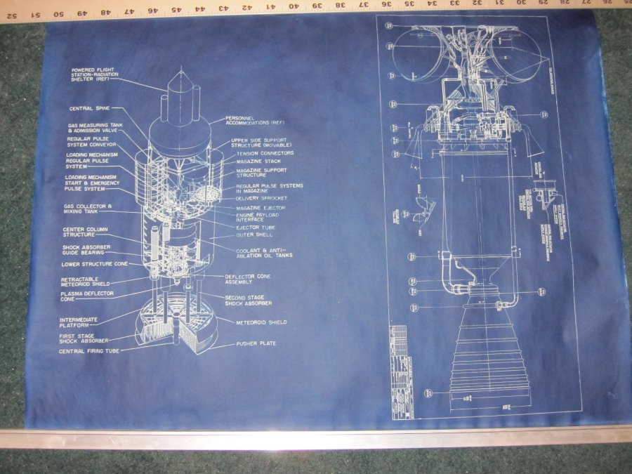
10-meter Orion, 12×18; $20. On hand: 1
NERVA diagram, 12×18; $20. On hand: 1
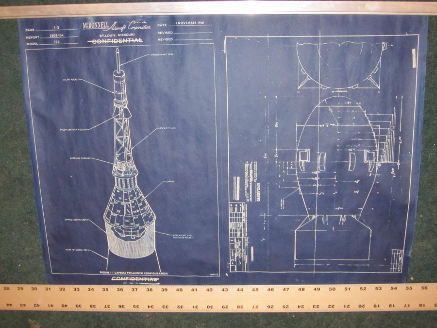
Mercury prelaunch configuration, 12×18; $20. On hand: 2
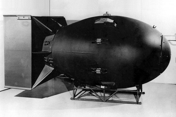
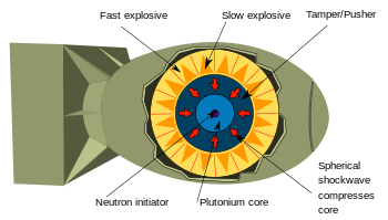
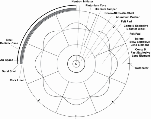
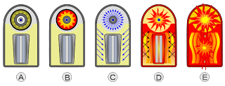
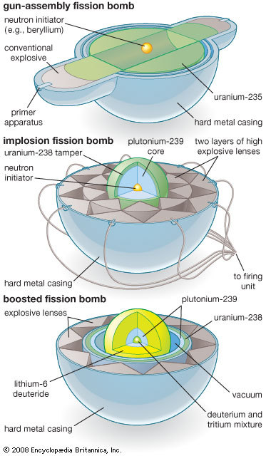
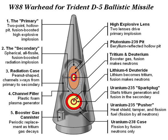
Fat Man atom bomb, 12×18; $20. On hand: 2
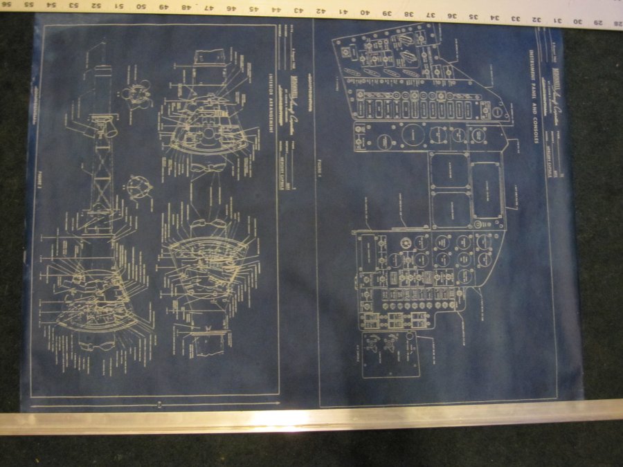
Mercury inboard views,12×18; $20. On hand: 1
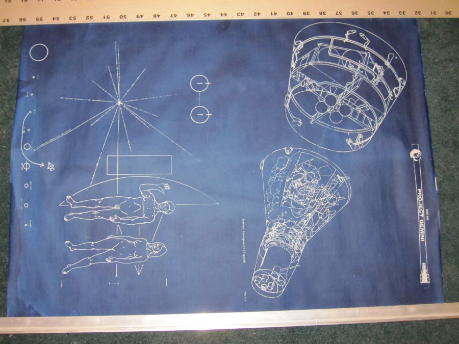
Pioneer plaque, 12×18; $20. On hand: 2
Gemini capsule, 12×18; $20. On hand: 5
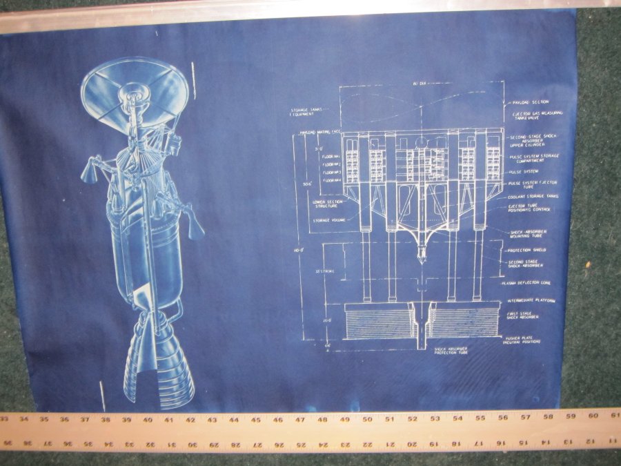
4,000 ton Orion propulsion module, 12×18; $20. On hand: 1
XNJ-1 nuclear turbojet, 12×18; $20. On hand: 3
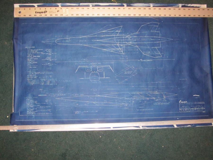
X-15A-3 delta-wing, 12×18; $20. On hand:
Gemini (see above)
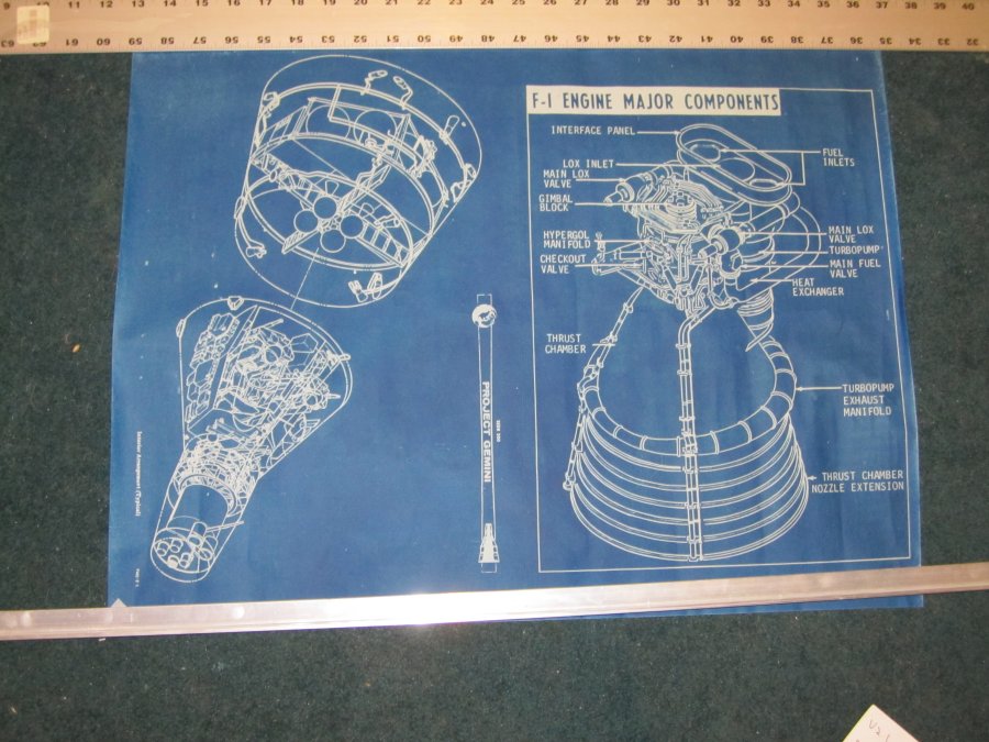
F-1 engine components, 12×18; $20. On hand: 3
Aug112011
For no verifiably useful reason, I decided to take a look at my Blog Stats. Shows stuff like how many visits the blog gets, where people click links to come to it, which posts got how many visits, etc. One set of stats is “search terms” people use to come to the blog. Below is what’s listed for yesterday. Note that people don’t seem to be coming to the blog for fantastic photography of cats or lightning, or unbuilt aircraft & spacecraft projects, or political rants & news: no, people want Hot Redheads.
Every single data point tells me that if I want to make money, I’ve gotta turn The Unwanted Blog into a hardcore pornaterium.———————–
These are terms people used to find your site.
Yesterday
| Search | Views |
|---|---|
| redhead | 35 |
| awesome | 20 |
| unwanted blog | 15 |
| focke wulf fw 198 | 14 |
| the unwanted blog | 8 |
| hot redhead | 8 |
| messerschmitt me-328 3-view | 7 |
| hot red head | 6 |
| juno 2 irbm | 5 |
| natf | 5 |
| f-111b | 5 |
| x-24 | 5 |
| hot redheads | 4 |
| are smurfs evil | 4 |
| nuclear lightbulb | 4 |
| aircraft cutaway | 4 |
| world trade center jumpers | 4 |
| fokker/republic d-xxiv alliance | 4 |
| chain lightning 1950 film | 4 |
| plans japanese submarines wwii | 3 |
| why are smurfs evil | 3 |
| lhx | 3 |
| gold ak 47 gun | 3 |
| terminator hk aerial | 3 |
Feb112010
I’ve been digging out the old files for the book project previously described HERE. By far the largest part of the book was/is going to be on propulsion systems. Now, this may be due to the fact that propulsion systems for spacecraft were my schtick, professionally; but I like to think that it’s actually because compared to the propulsion system, everything else (navigation, life support, power, etc.) is pretty secondary. Think of it this way… if tomorrow Microsoft announced that they had developed a perfect closed-system ecology perfect for long duration spaceflight, the general response would be a collective yawn. But if someone tomorrow announced that they figured out how to make a practical and affordable warp drive that could send you to the stars at ten times the speed of light, people around the world would start slapping together starships the day after. To hell with closed ecologies… just pack an assload of canned Spam.
<> Anyway, one of the files I’ve got is the outline of the propulsion system section. My idea was to break all technologies into several technological “eras,” as described in the book’s Introduction:
This book will show how to design and use your Spaceship to a level of detail adequate to avoid the usual pitfalls of most science fiction. To do this, the technology levels are divided into the following types:<> Anyway, one of the files I’ve got is the outline of the propulsion system section. My idea was to break all technologies into several technological “eras,” as described in the book’s Introduction:
1) Now
2) Real Soon
3) On the Horizon
4) Beyond The Horizon
5) Magic
The “Now” class of spaceship is what can actually be built today, with equipment more or less off the shelf, or new designs that make no noticeable advancements on existing equipment. This would include such things as conventional staged, expendable launch vehicles (from small to very large), to space capsules, small spaceplanes, Shuttle-type vehicles, basic inter-orbit tugs, lunar landers and the like. All would be powered by such propulsion systems as chemically fueled rockets – liquid, solid and hybrid; some use of low thrust systems like ion engines and resistojets. These technologies, used wisely, allow for the early commercialization of near-Earth space and the limited manned exploration of the Moon, Mars and some nearby asteroids.
The “Real Soon” class of spaceship would include the use of technologies that have received considerable ground testing, but have not been used. These are devices and technologies that the engineers behind them are virtually certain will work, but will require development. Such spaceships would include fully reusable two stage to orbit launchers, early single stage to orbit vehicles, solar sails, Mars landers, and nuclear thermal rockets such as the NERVA. There are a few materials of note in the “Real Soon” category that would be of interest, such as high temperature ceramics and aerogels. The “Real Soon” designs would, somewhat arbitrarily, encompass those available beginning around 2010-2030, and are the sort of technologies that would allow for true commercialization of near-Earth space (including the Moon and, possibly, near-Earth asteroids) and the manned reconnaissance of the inner solar system.
The “On The Horizon” designs would include the use of technologies that have received only very preliminary testing, and are largely “vaporware.” This class would include such things as airbreathing single stage to orbit vehicles, nuclear pulse vehicles, gas-core nuclear vehicles, laser-propelled launchers, early fusion and antimatter drives. These technologies, which may become available around 2030-2060, would allow for the low-cost commercialization of near-Earth space (including the Moon), tourism to Mars, and the manned exploration and exploitation of the entire solar system, with early missions to the Oort Cloud and Kuiper Belt.
The “Beyond The Horizon” vehicles would be where things start to get really interesting. These would include the use of technologies that scientists have only the barest preliminary theories of, and engineers are currently very uncertain as to how to even contemplate their use. However, it is in this area where the first interstellar propulsion systems become available. Pure antimatter “photon” drives, Bussard ramjets, advanced pure fusion drives and the like. “Beyond the horizon” technologies have the potential of making the entire solar system accessible as the steam engine made the world accessible. These technologies may become available in the second half of the 21st Century and beyond.
“Magic” technologies are those for which even a theoretical basis is almost totally lacking, or which current theory does not support. Warp drive, hyperdrive, jump drives, wormholes, time travel, gravity generators, zero-point energy generators all fall into this category. They have the potential of making the entire universe accessible. However, with the highly hypothetical nature of these technologies, putting even a vague handwavy date on them is not reasonable. They may be impossible; they may equally be demonstrated within a few years.
———————-
So, here’s the general outline of what the propulsion system was expected to look like:
———————-
Basics:
Spaceship Physics 101
The rocket equation – Read it, Learn it, Live it
Rocket engine design basics
Basic Rocketry
Thrust Vectoring
Jetevator
Jet tabs
Jet Steering
Secondary Liquid Injectant
Rotating Asymmetric Nozzle Extension
Supersonic Splitline
Differential Throttling
Relativistic Travel & Effects
Types of propulsion:
Available Now:
Siege Engines
Steam Rockets
Compressed Gas
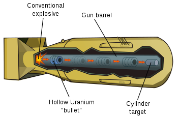
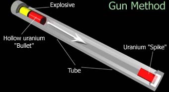
Guns
Chemical Rockets
Solid rockets
Liquid rockets
Monopropellant
Bipropellant
Bimodal
Liquid engine design features
Shock diamonds
Hybrid Rockets
Hypersolids
Pressurant vs. pumps
Electrical Propulsion Systems
Ion engines
Hall Effect Thrusters
Resistojets
Arcjets
Turbojets
Ramjets
Balloons
Available Real Soon:
Advanced Chemical Rockets
Expansion-deflection nozzles
Aerospike nozzles
Plug cluster
Dual bell
Hypersolids
Goddard’s Turbo-Prop Rocket
Rotationally Augmented Thrusters
Nuclear Thermal Rockets
Nuclear ramjet
Solar Sails
Solar Photon Thruster
Laser /Microwave Sails
Solar Thermal engines
VASIMR
Rotary Slings
Rotavators
Slingatron
Pulley Drives
On The Horizon systems:
Scramjets
Ducted Rockets and Ejector Ramjets
Liquid Air Cycle Engines
Pulse detonation engines
Gas core nuclear
Nuclear/MHD “Torch”
LANTR
Nuclear lightbulb
Nuclear pulse (Orion)
Nuclear Pulse (Medusa)
Nuclear Pulse (Helios)
Laser Launch
M2P2
MagSail
Railguns
Mass Drivers
Antimatter: Fuel of the Future.
An Antimatter Primer
Antimatter Steam Rocket
Antimatter ramjets
Antimatter turbojets
Anti-Proton Initiated Fusion
Muon Catalyzed Fusion
Pellet Stream Propulsion
Sail Beam
Light Gas Balloon Tunnels
Hydrogen Balloon Ramjet Tunnels
Advanced Artillery
Scramjet Guns
Light Gas Guns
Compressed Gas
Combustion Driven Piston
Falling piston
Underwater gun
Thermal Bed Gun
Nuclear Reactor Gun
Nuclear Bomb Gun
Electric Discharge Gun
Beyond The Horizon:
Launch Loop
Matter/Antimatter Photon Rocket
Bussard Ramjet
Catalytic Ramjet
Ram Augmented Interstellar Rocket
Exotic Chemicals
Metastable Helium
Monatomic Hydrogen
N20 (Nitrogen-Twenty Buckysphere)
Magic:
Alcubierre Warp Drive
Krasnikov Tunnel
Quantum Teleportation
Vacuum Point Energy systems
Wormholes
Artificial Gravity
Inertialess Drives: General
Inertialess Drive: Negative Matter
Inertialess Drives: Dean Drive and others (i.e. BS)
Forwards’ Spin Drive
If I’ve missed anything, and I almost certainly have, feel free to drop a note.
